Build Log
Tensegrity was originally a project built during the southern hemisphere summer of 2014/2015 for Kiwiburn 2015. I had the original concept shortly after the previous Kiwiburn where I built “The Sensorium”. The Sesnorium allowed me to learn many new skills, as my electronics knowledge had atrophied since high school and first year Physics, but Tensegrity was way more ambitious.
The idea was: a 3m high cylinder of criss crossing metal pipes with led strips, with the whole structure spun at 1-2 revs per second atop a 3m high pole!
We didn’t quite end up doing that, but here’s a video of the final product:
- Conception
- Electric Motors and AC drives
- Simulation
- Metal Structure
- Bearing Construction
- Power and Electronics
- Software
- Scaffolding
- Test Run
Conception
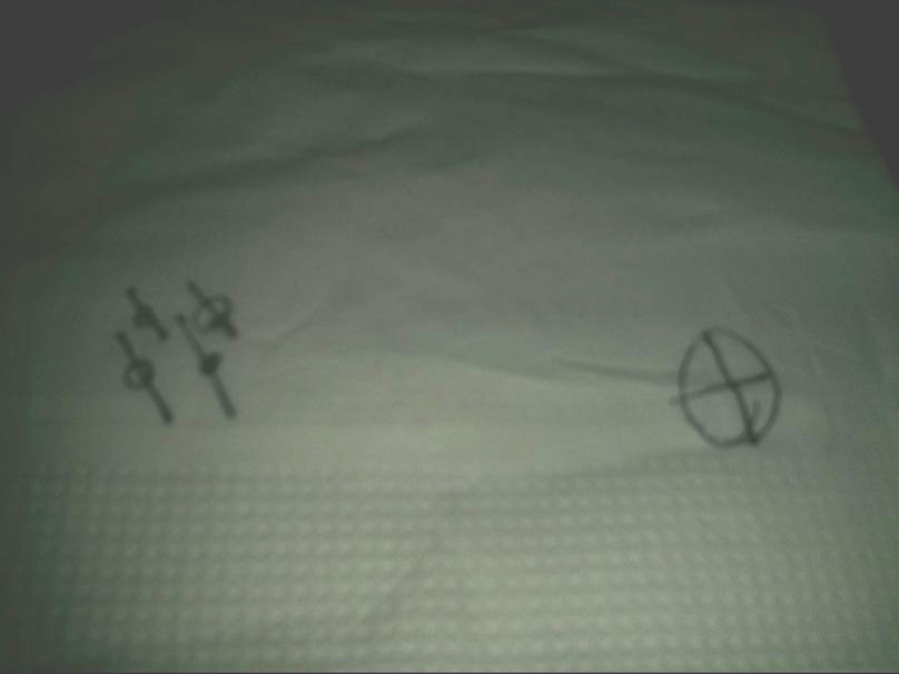
Things began at Fidel’s cafe discussing art projects ideas over the cliche napkin.
I was being quite ambitious; I knew nothing about slip rings, welding, or working with metal when I started. As a scientist and software developer, I’m happy working with complex ideas and creating elegant representations of abstract concepts, but creating giant spinning metal sculptures in the real world was something very different!
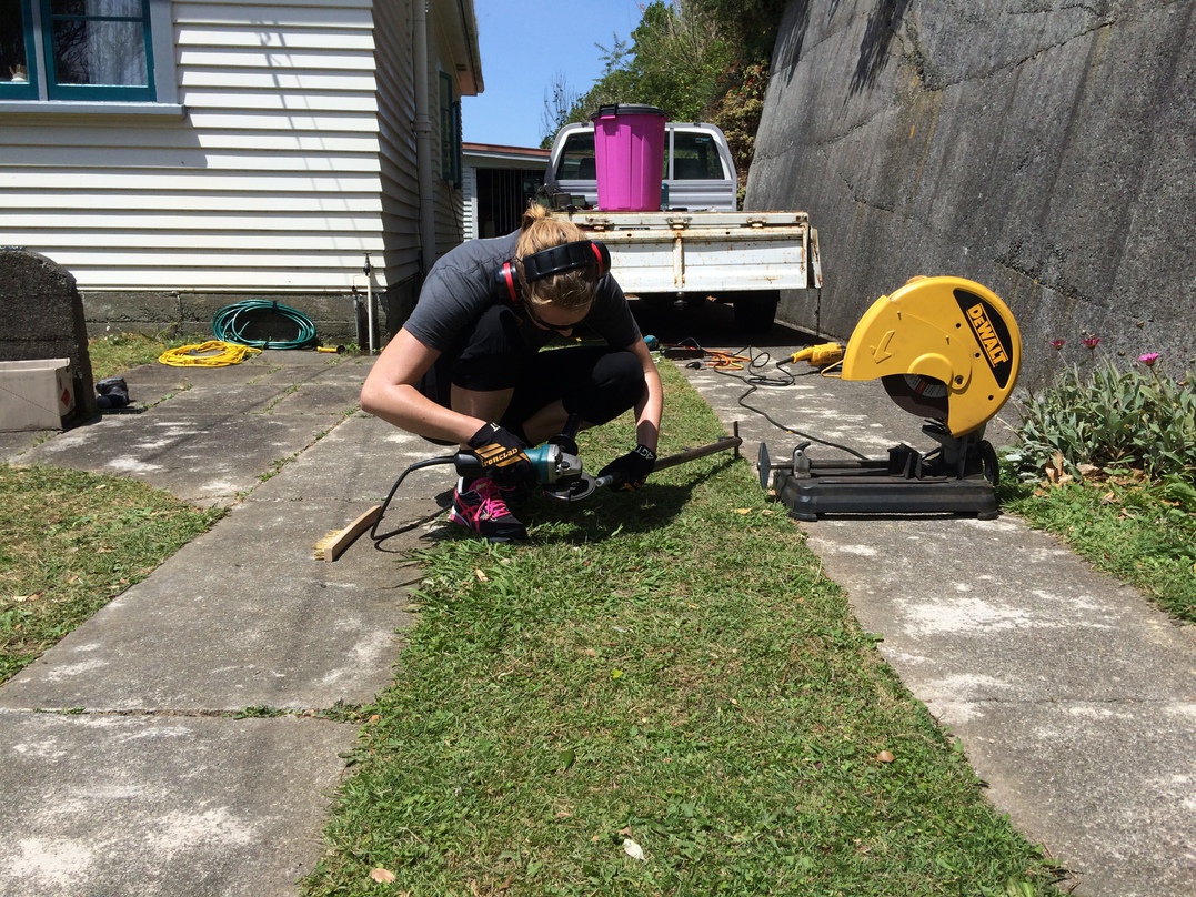
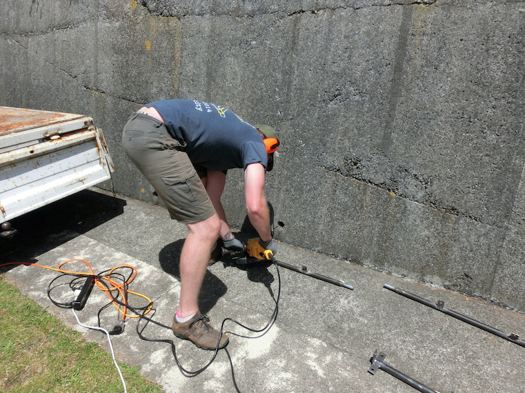
I called out to my community for people keen to help me with this audacious idea, and had many wonderful people offer assistance. The most valuable in making the project succeed (and in easing my trepidation at trying to pull this off) was that of Patrick Herd who took the lead on the mechanical engineer and construction techniques, and Felicia Ullstad who helped with the metal working and construction.
Tensegrity is what I’d consider my first serious foray into doing art installations, and while I’m very happy with the end result, the real joy came from everything I learnt during it and seeing other people’s reactions at Kiwiburn!
Without further ado, here’s the story of it’s construction…
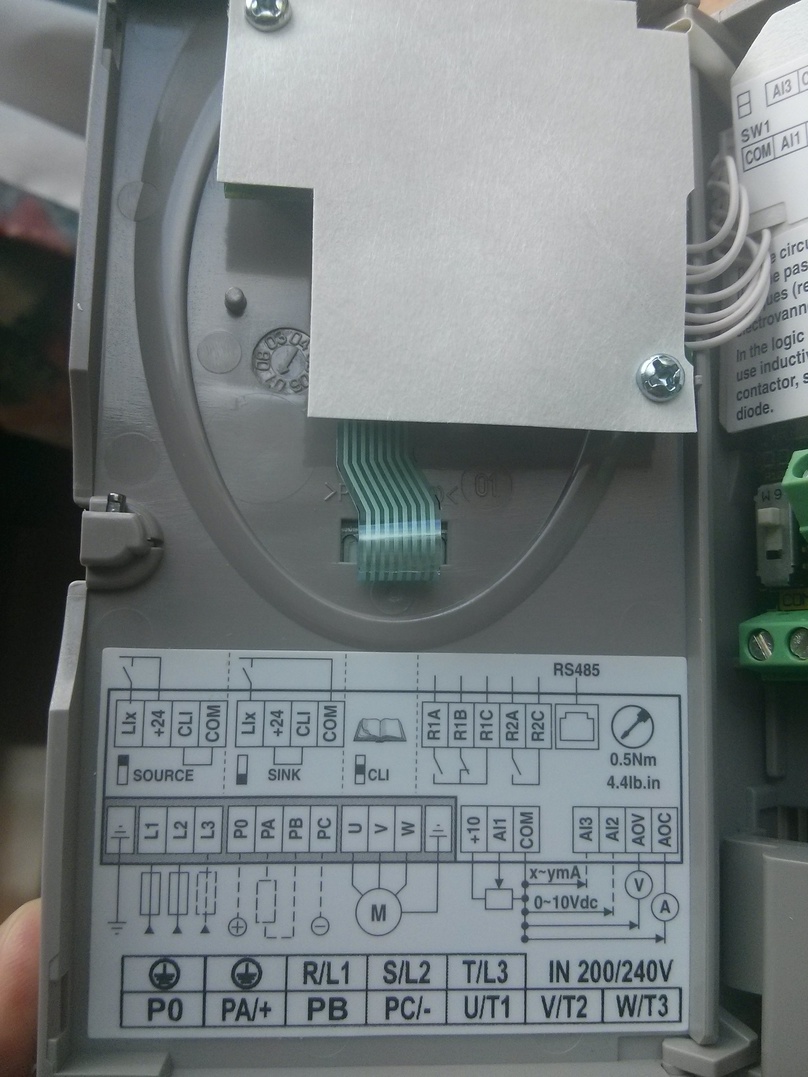
Electric motors and AC drives
Patrick, getting into the idea, browsed Trademe and found both a second-hand motor and an AC drive. I bought them up, along with a Himel box to store and protect the gubbins from the weather.
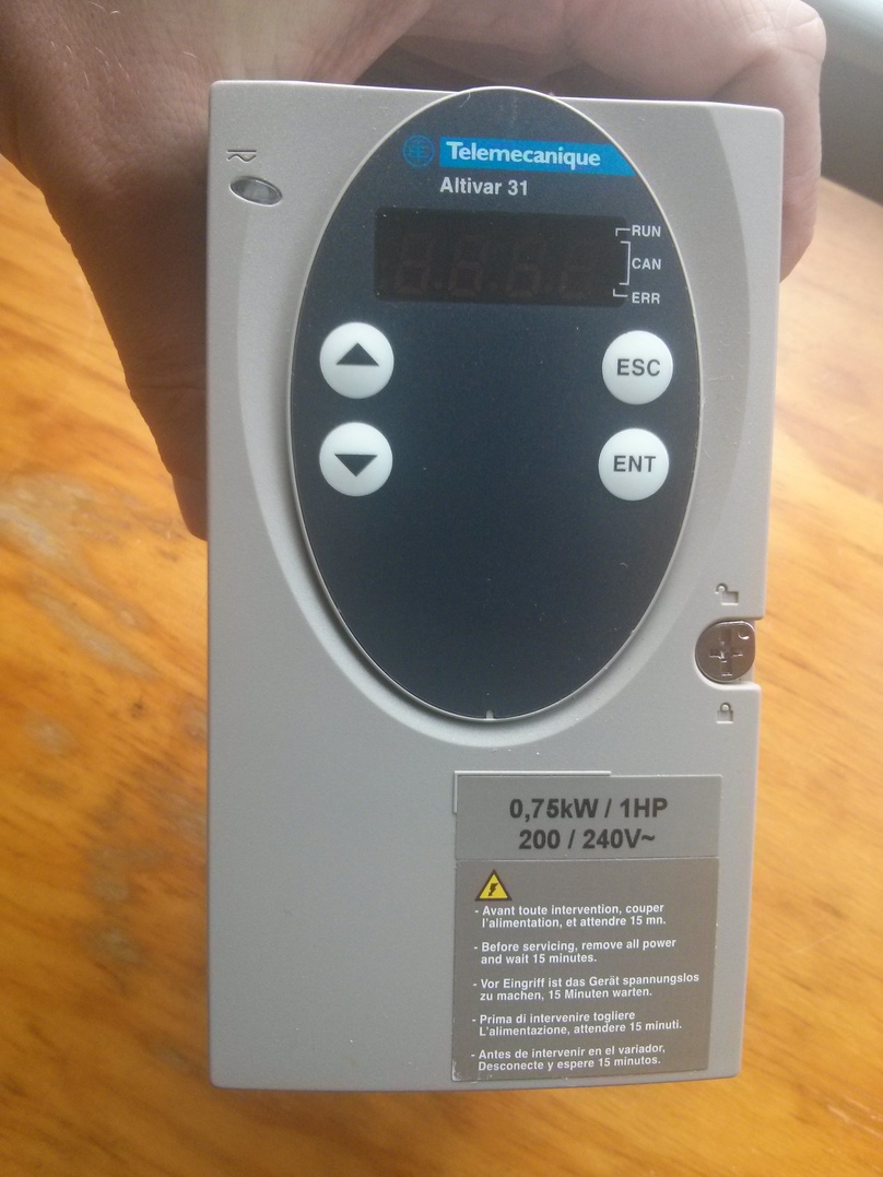
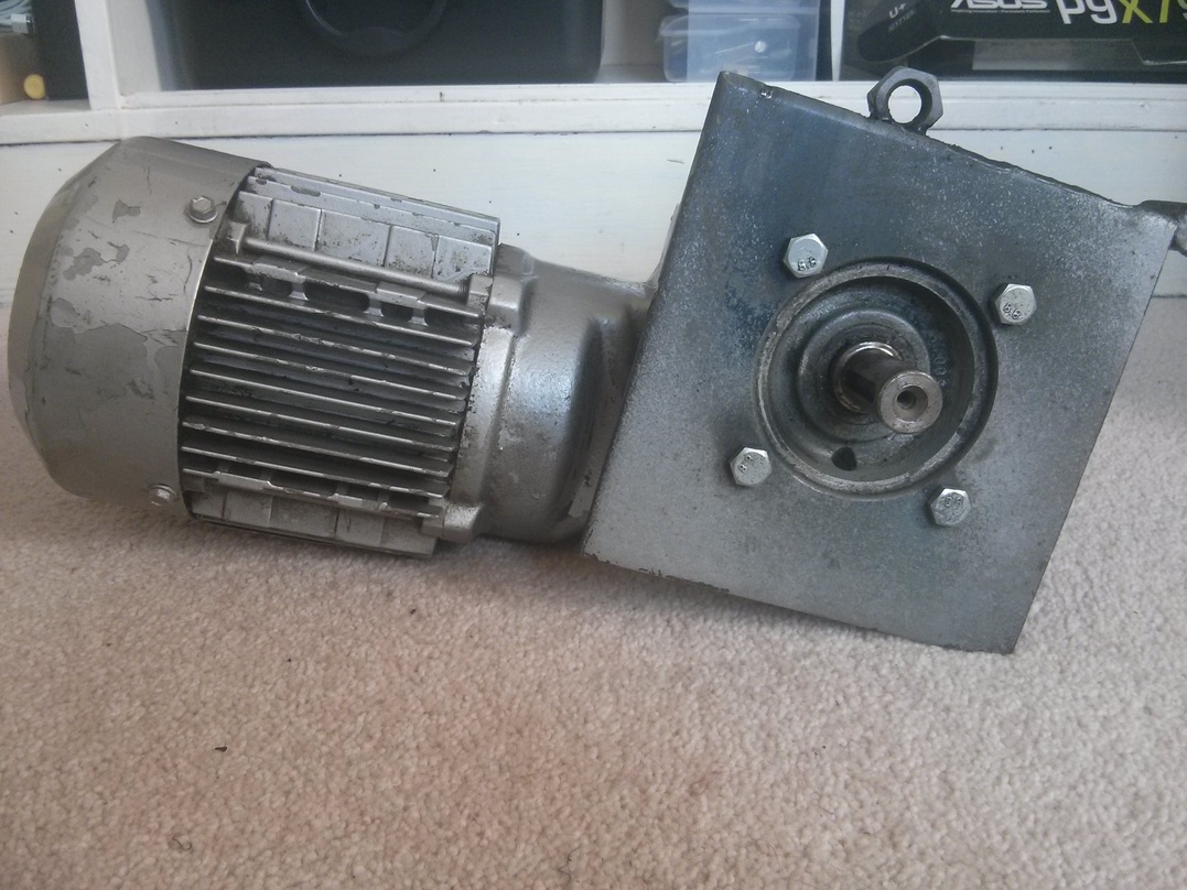
It was as grunty as anticipated. Only 60 rpm (1 rev/sec), but just try stopping it from turning! And while a small axle spinning at that speed looks slow, the outer edge of a 2m diameter cylinder spun by it would travel approximately 6.3 m/s!
Simulation
Before starting on the construction, I wanted to be able to visualise what it’d look like and make sure the concept was right. I also wanted to be able to start programming visual patterns before the main structure was completed. For the Sensorium, I only had one plasma-like effect due to time constraints. I was disappointed not have more patterns ready to go and I didn’t want to be caught out in the same way this time.
Also, when your art is large, it’s much harder to play around with ideas in reality than from the comfort of your computer desk… ok, so I could have done this because it had a wireless access point (see later), but still.
I used Processing to create a simple 3d representation of the main parts. The code of which is part of the project’s github repo.
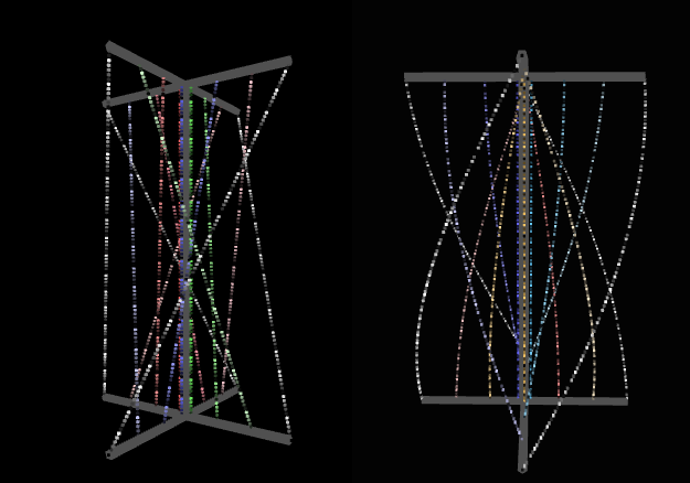
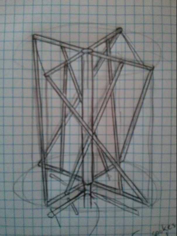
The image on the right is the design we went with, but the image on the left is the original concept. The original concept is the reason it’s called tensegrity, and has more connection to the concept of tensegrity. The longer story is that it mimics the shape of a tension structure that my really old evolutionary spring/physics experiment biobox would often stabilise with.
As a teenager, it fascinated me why a cube of springs would stabilise to such a shape, and it was only years later that I learnt there was a word for it.
Beyond just allowing me to simulate LED patterns, the simulation had some other benefits:
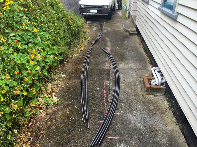
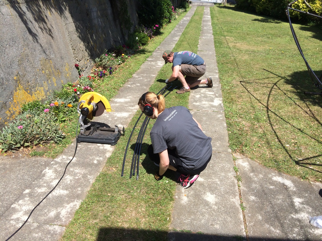
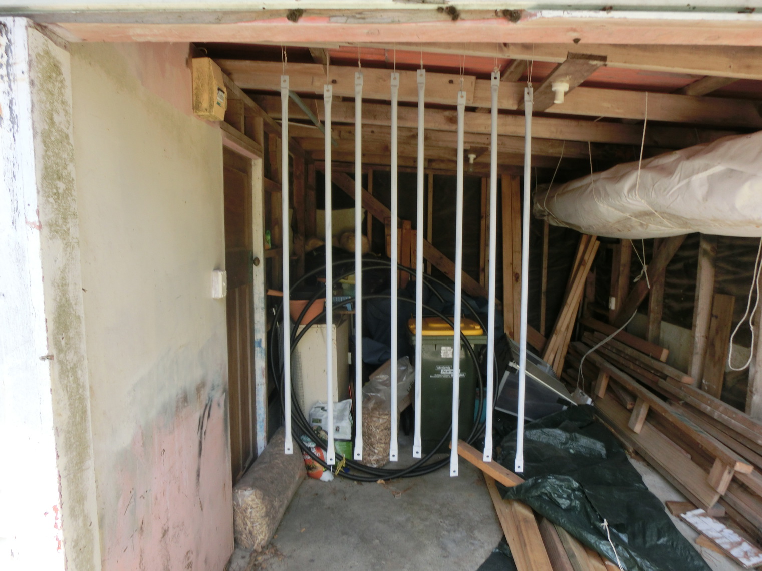
- It worked out the measurements of the curved struts between the arms. These measurements were necessary for cutting and bending the metal piping we ended up using. Similarly, it meant I could order the right amount of LED tape needed. While this would be possible to solve with pen, paper, sufficient maths and geometry knowledge, I’m lazy and also wanted to be able to alter the dimensions and not have to recalculate everything.
- It creating pixel layout files for each channel of openpixelcontrol (OPC) data which could be read by a number of pattern generator frameworks.
- It created a fadecandy server config file for mapping OPC channel data to the physical layout of fadecandies and strips (see later).
- Most awesomely, it has really basic OPC server to allow me to start writing effects that directly controlled the simulation. All I would have to do in order to move to using the effects on the finished physical product is change the IP address the pattern generator was sending data to.
Of course, all this functionality was only in the finished product and it took me several refactorings and iterations to get to it.
A side benefit of creating this simulation is that we are discussing the idea of letting people (such as design or computer science students at local schools) submit patterns to us before an event so that they can see their light pattern on the final product. With a simulation, they can test the patterns out before submission.
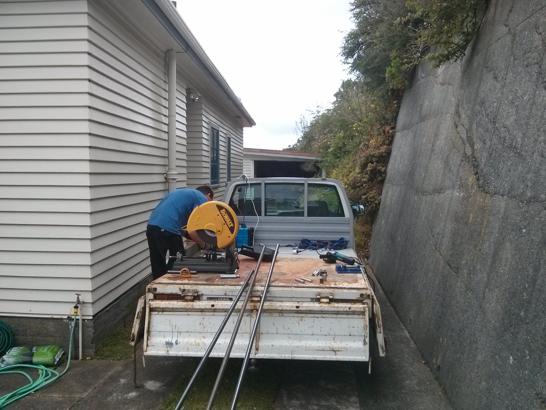
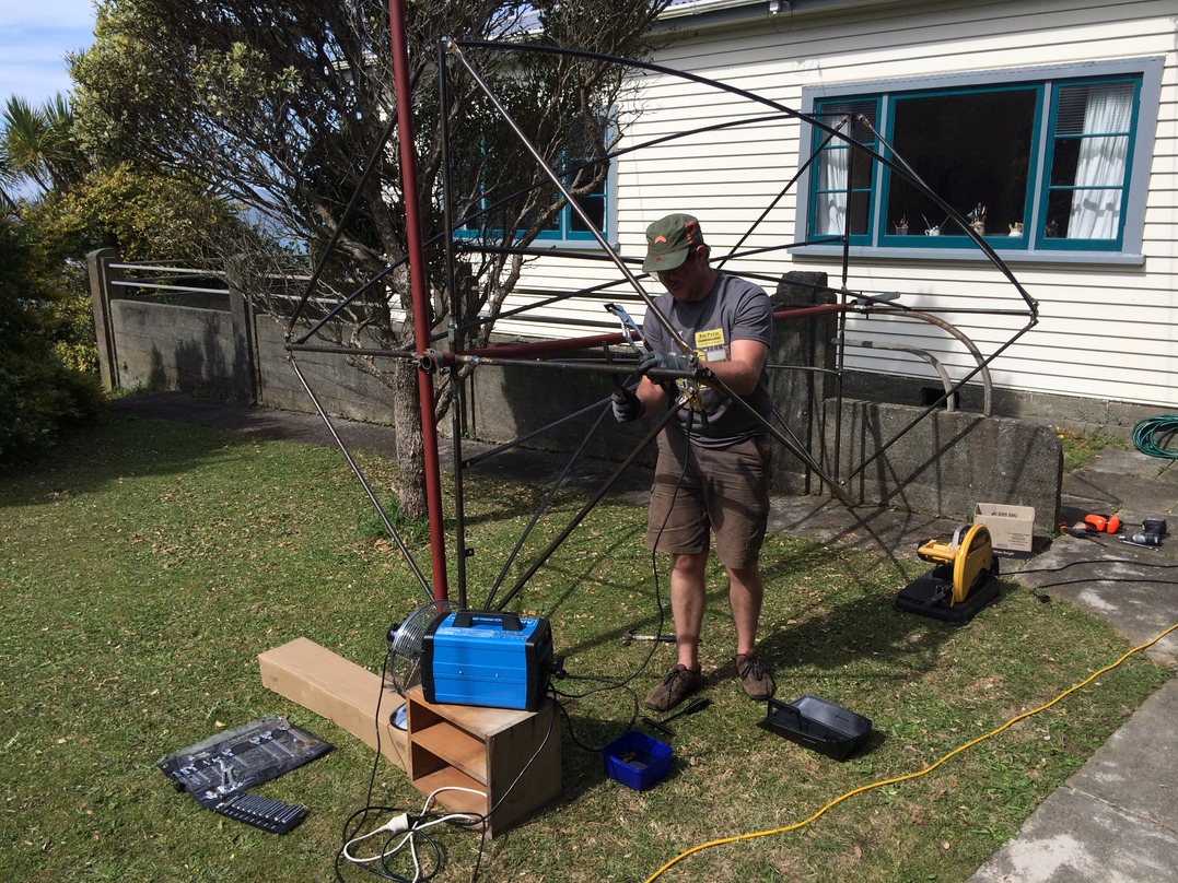
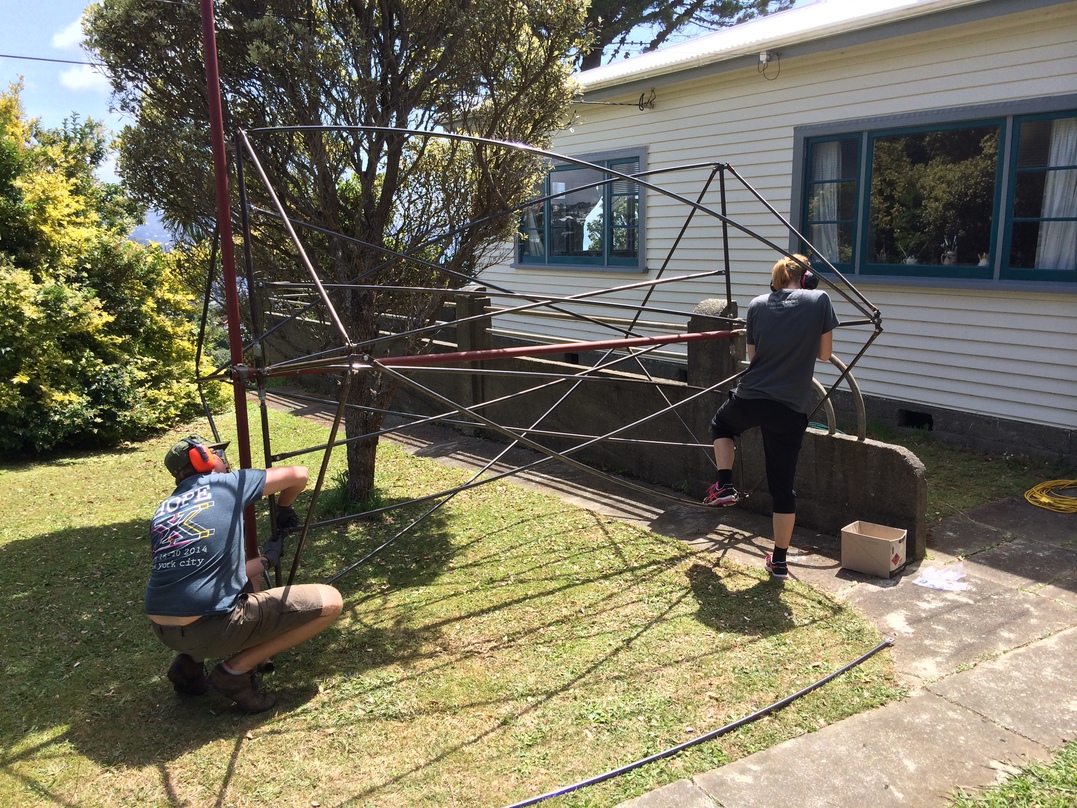
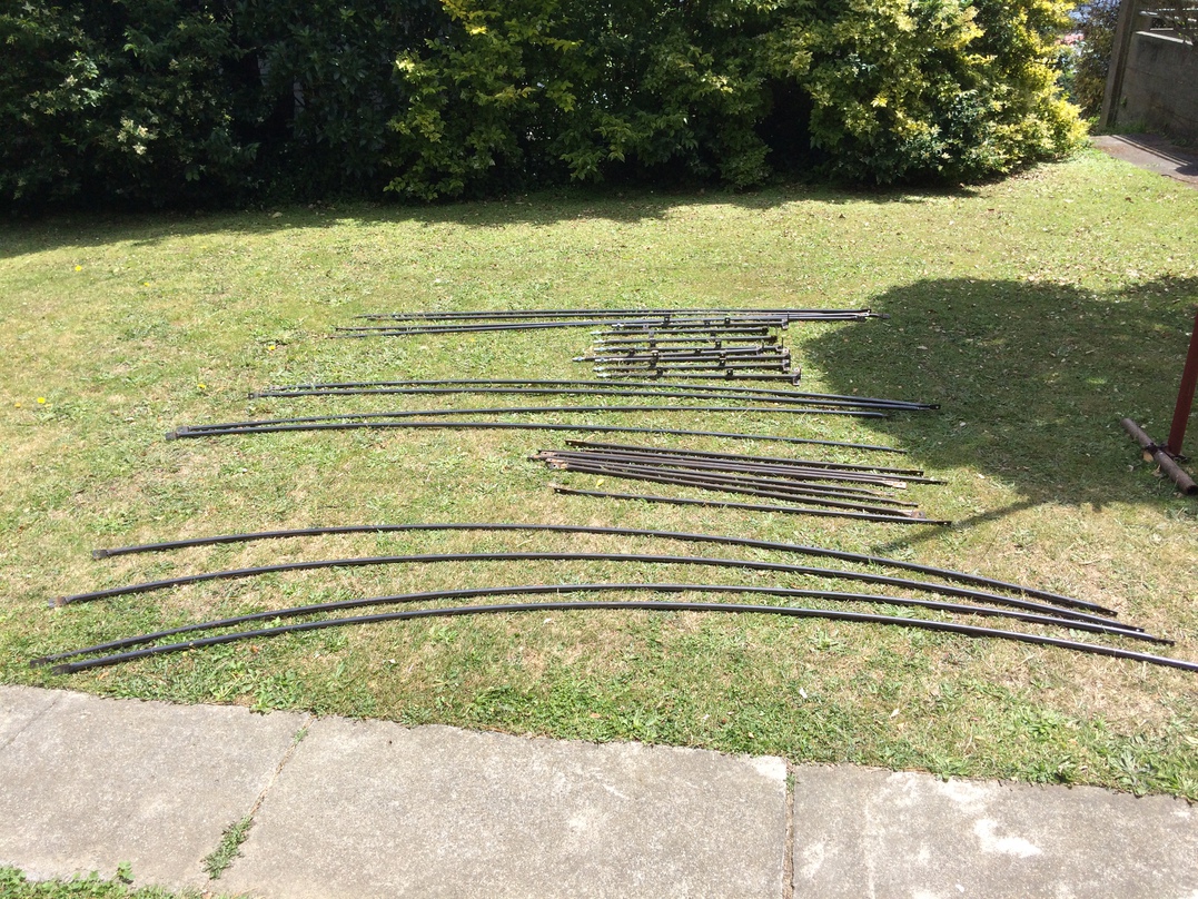
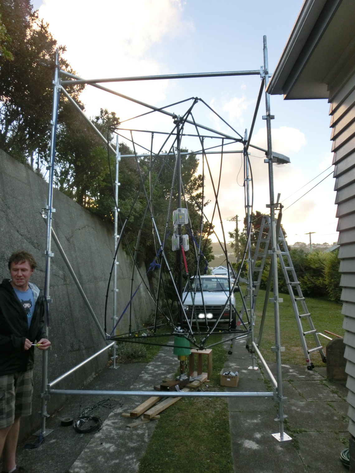
Metal structure
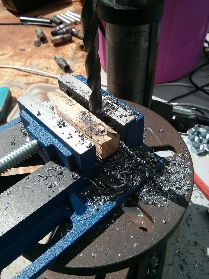
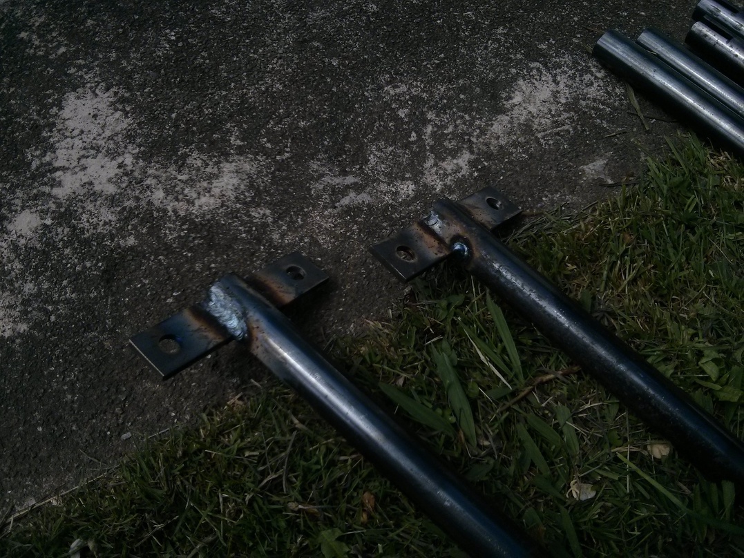
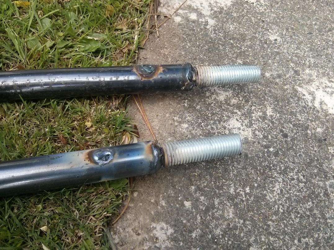
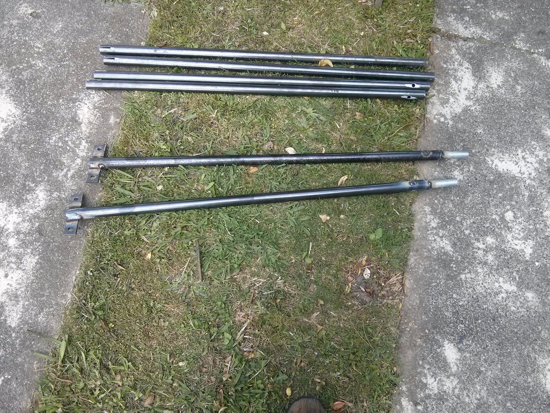
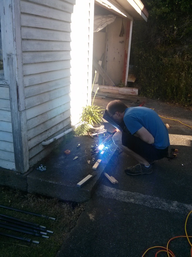
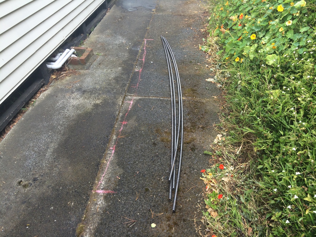
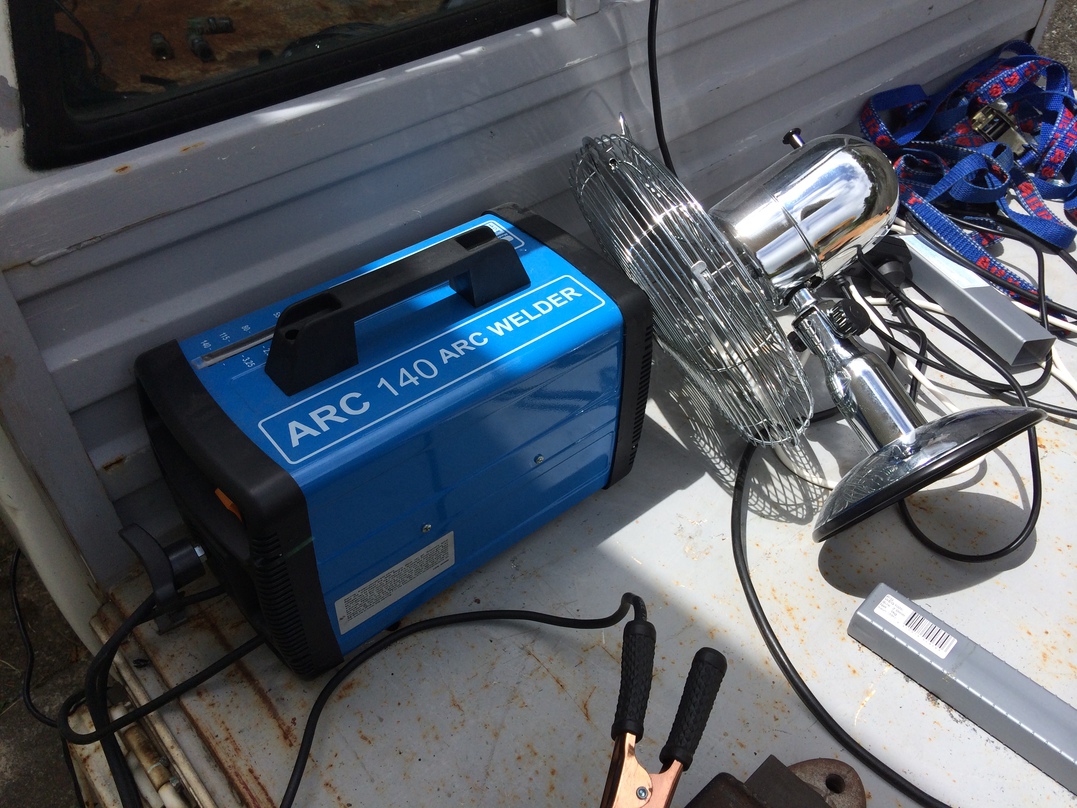
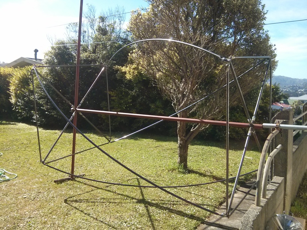
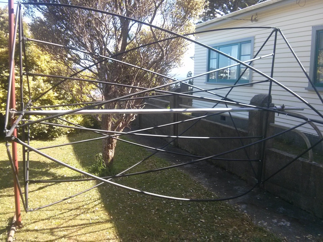
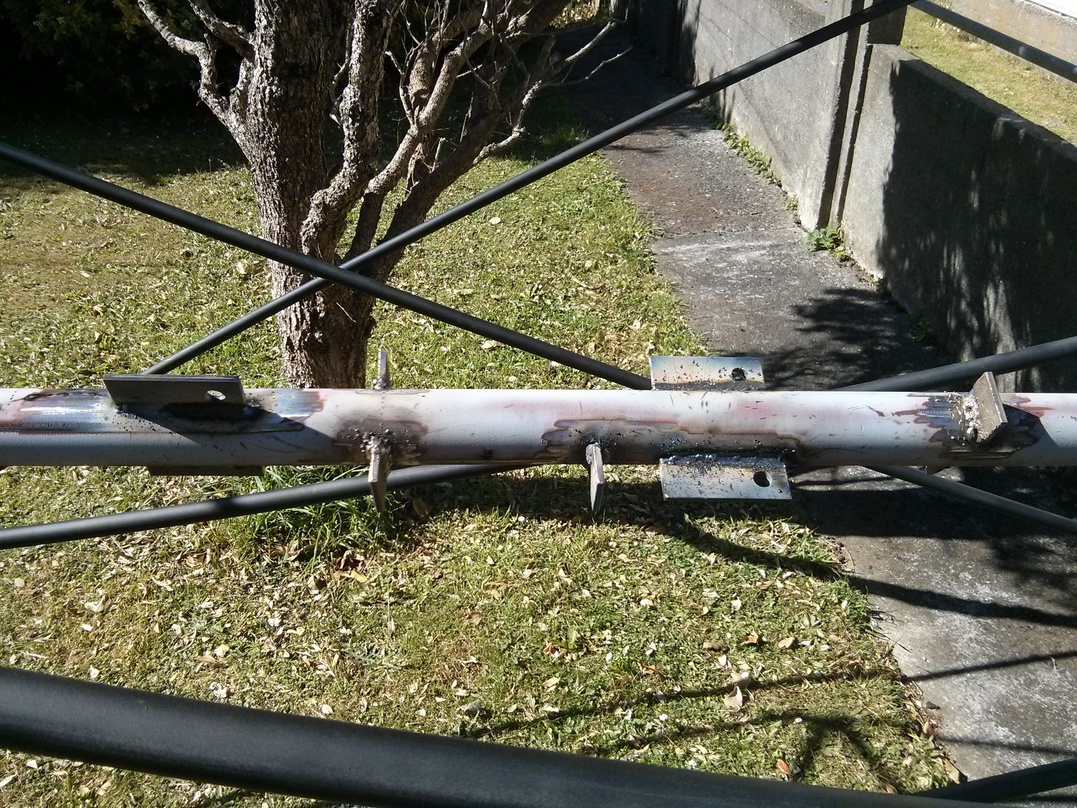
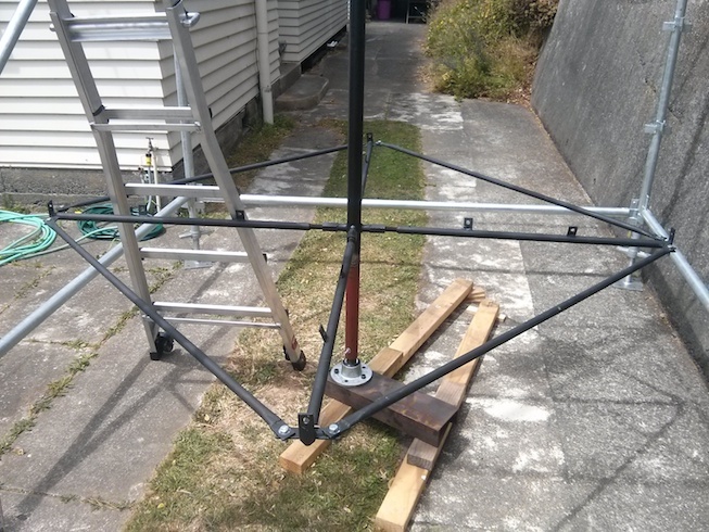
Once the structure was confirmed, Patrick had a plan to turn it into metal.
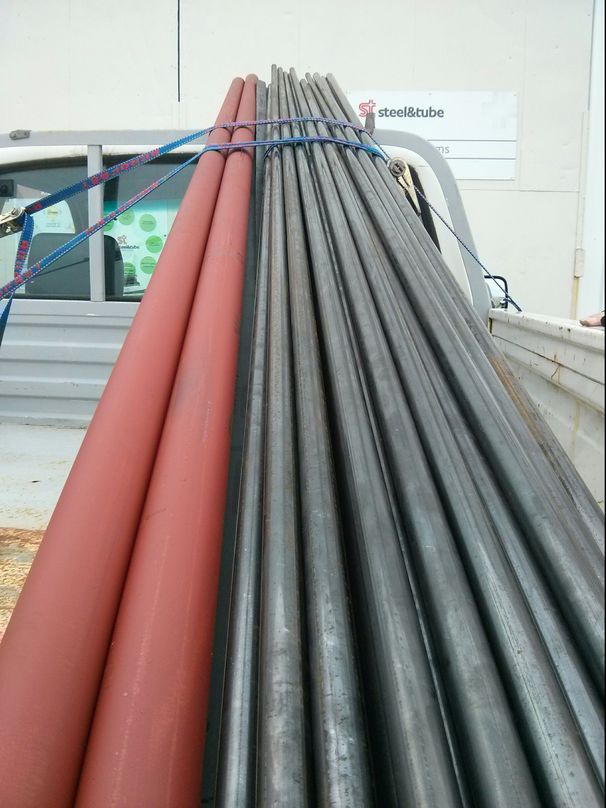
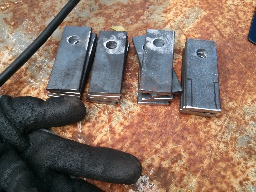
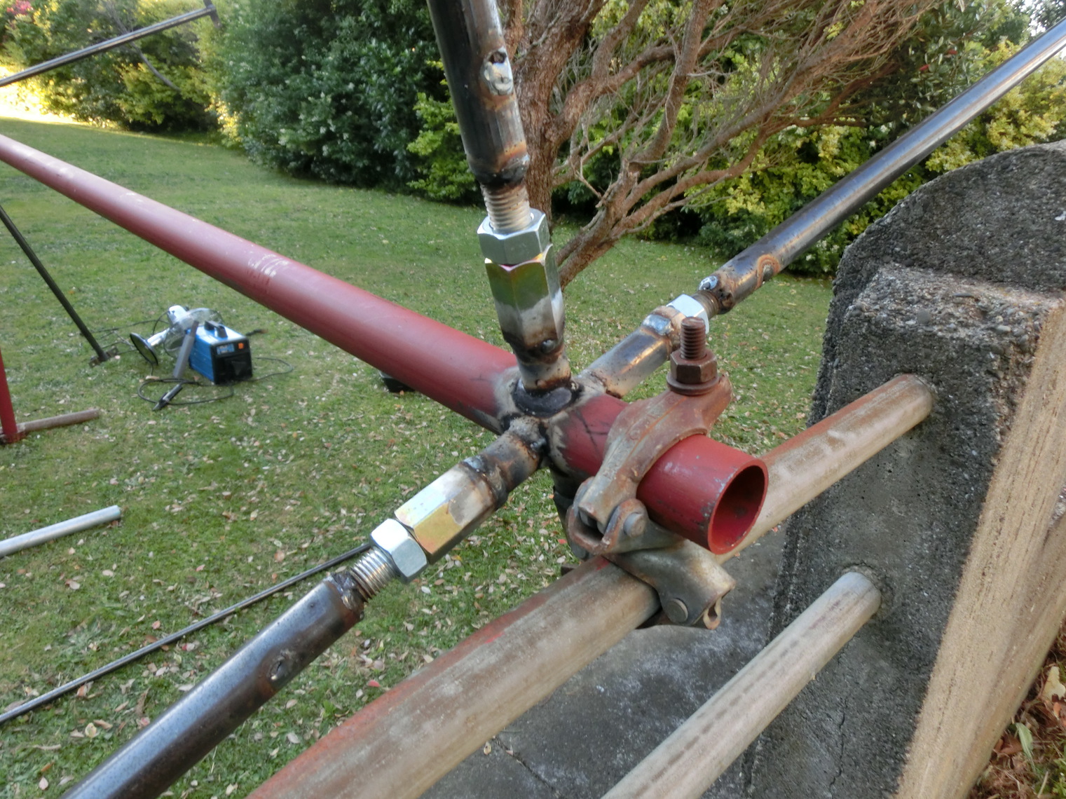
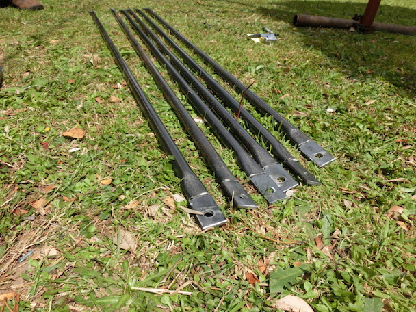
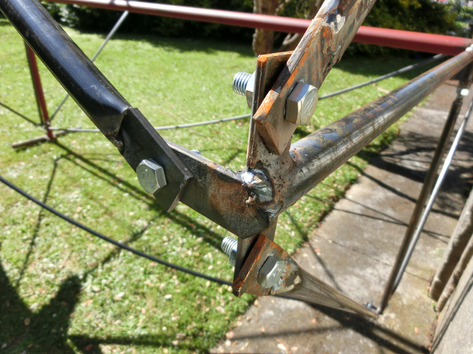
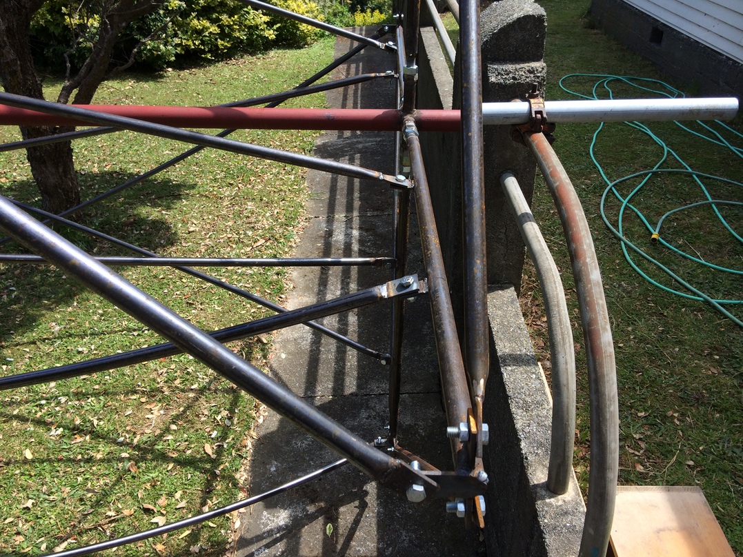
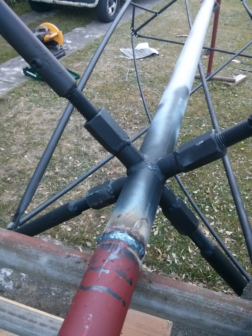
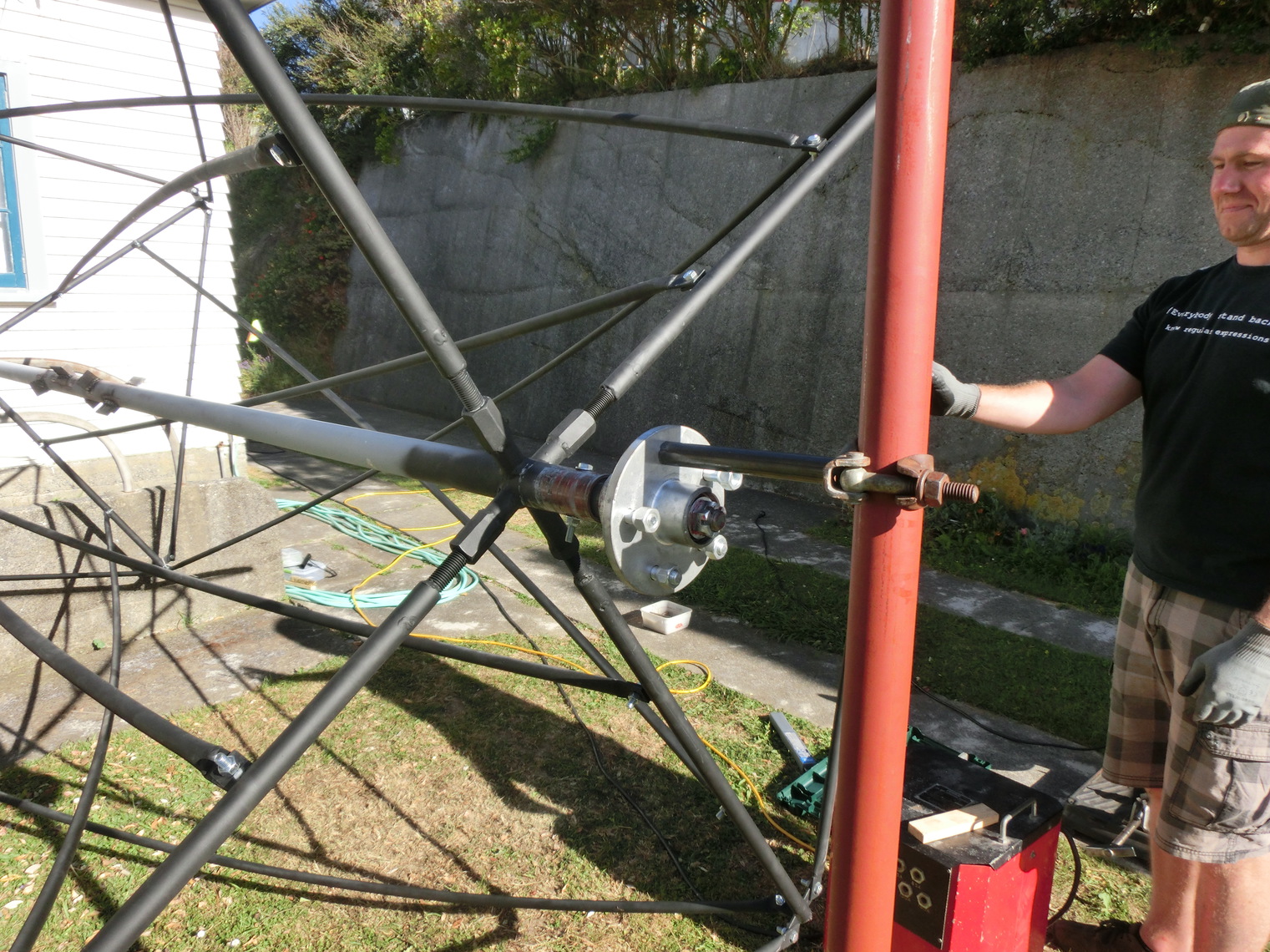
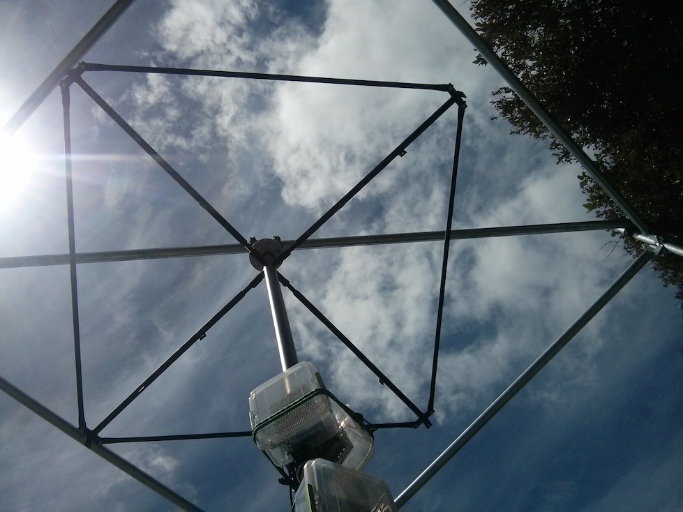
Patrick’s vision for the structure, with the additional constraint that it had be transportable, was to have a centre axle made of scaffold pipe with coupling nuts welded to it. Four arms at the top and bottom would then have matching size threading spot-welded into them. Each arm could be screwed into place and their distance adjusted to match any measurement errors due to our backyard manufacturing.
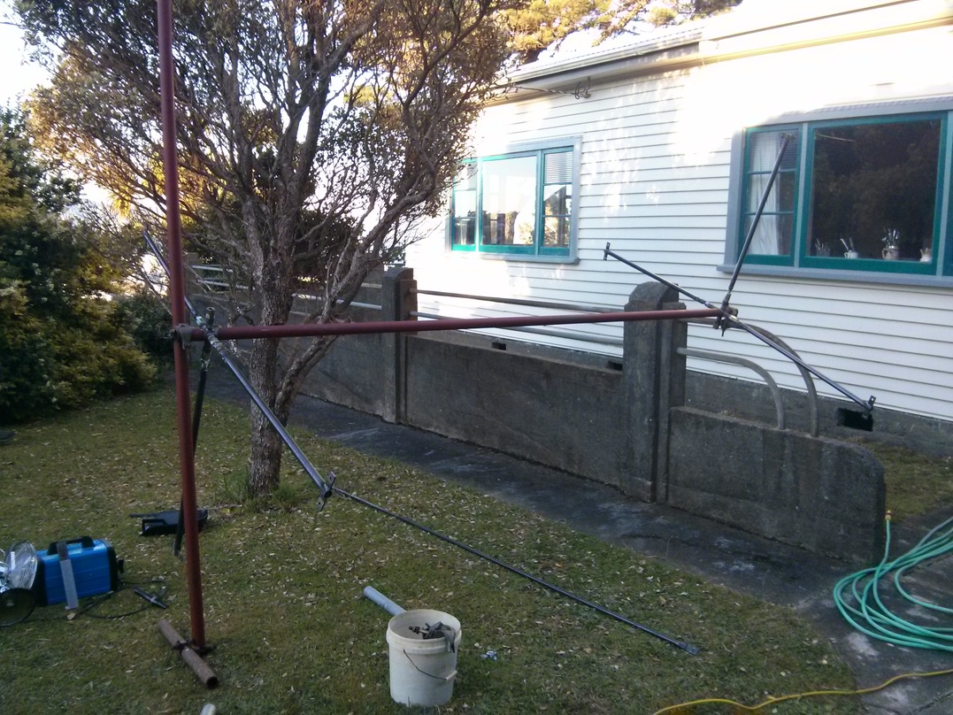
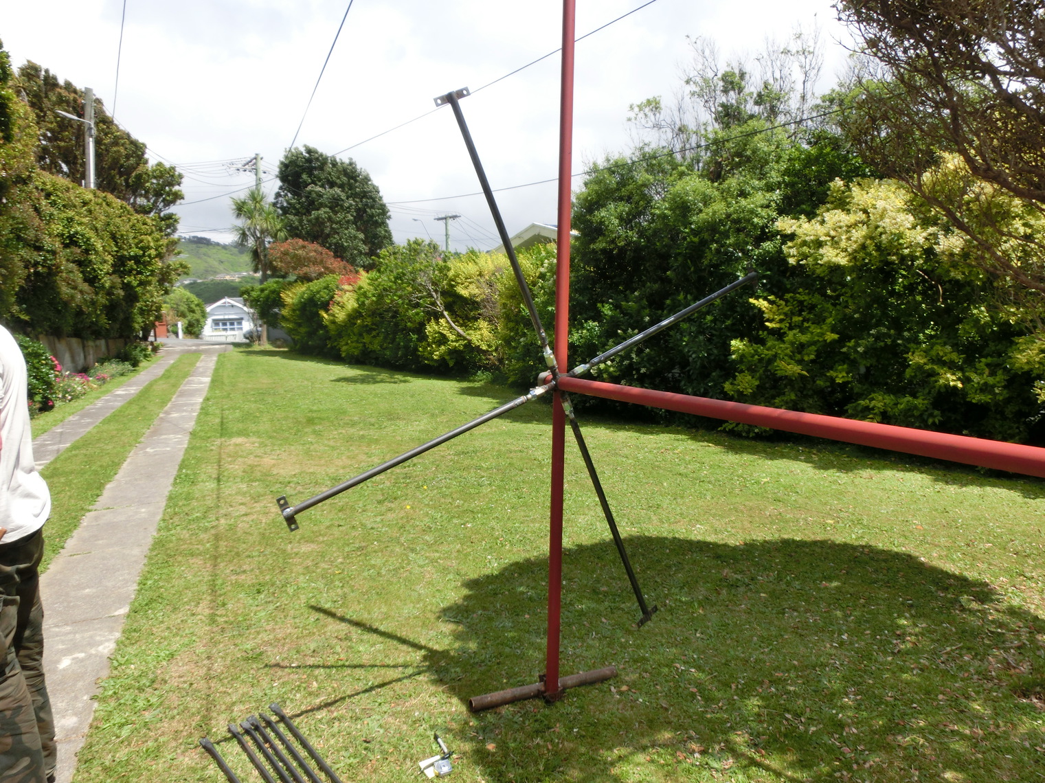
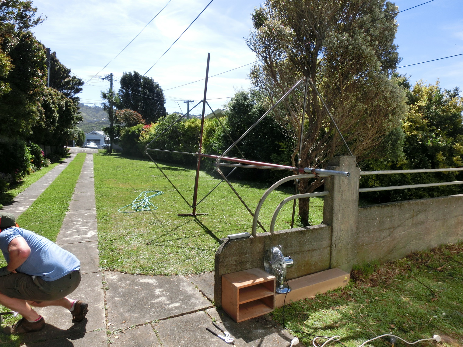
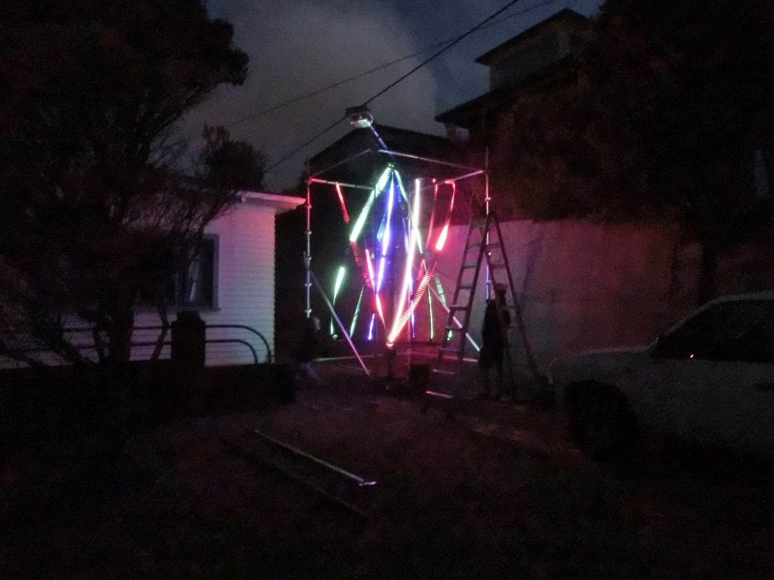
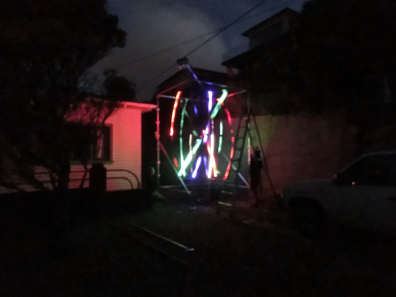
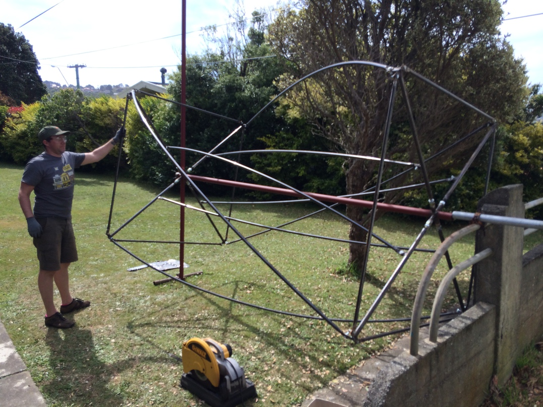
Here it is in motion:
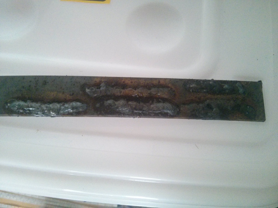
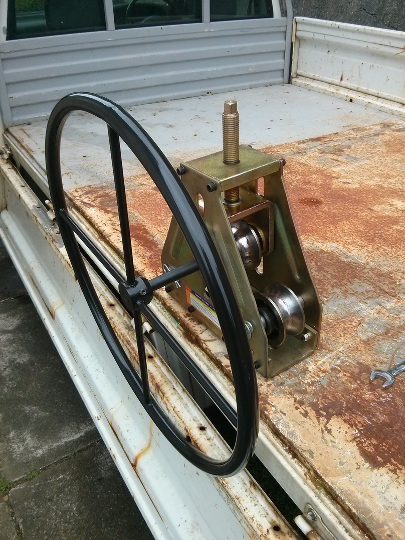
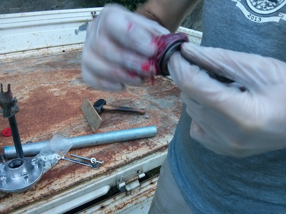
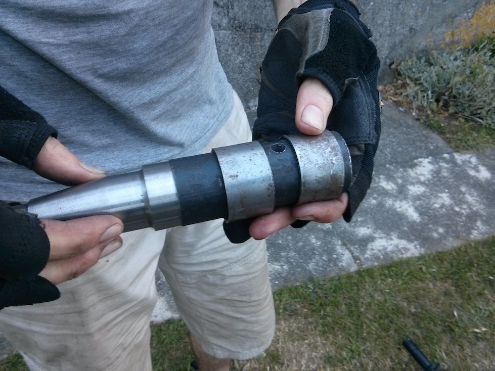
Bearing construction
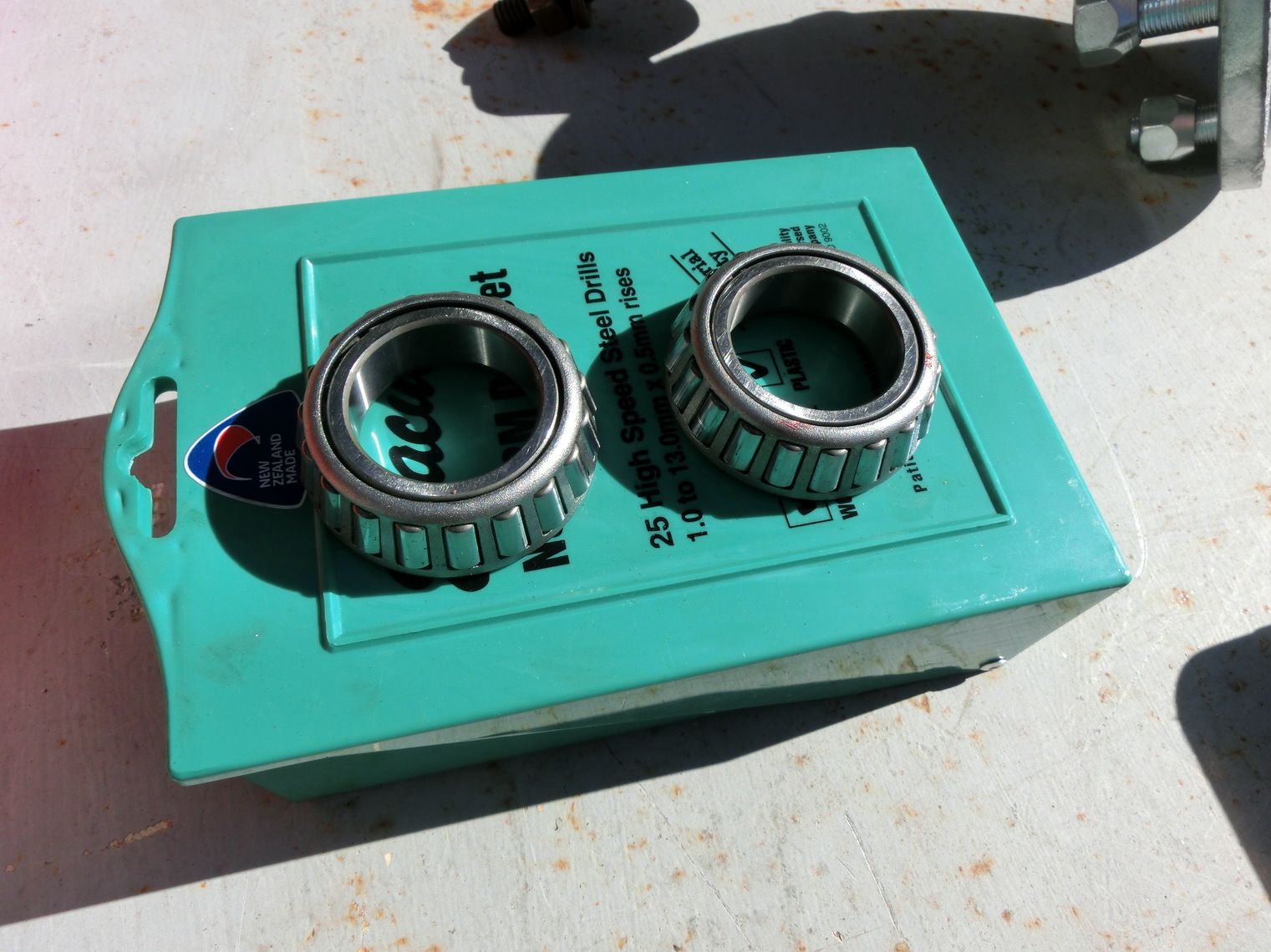
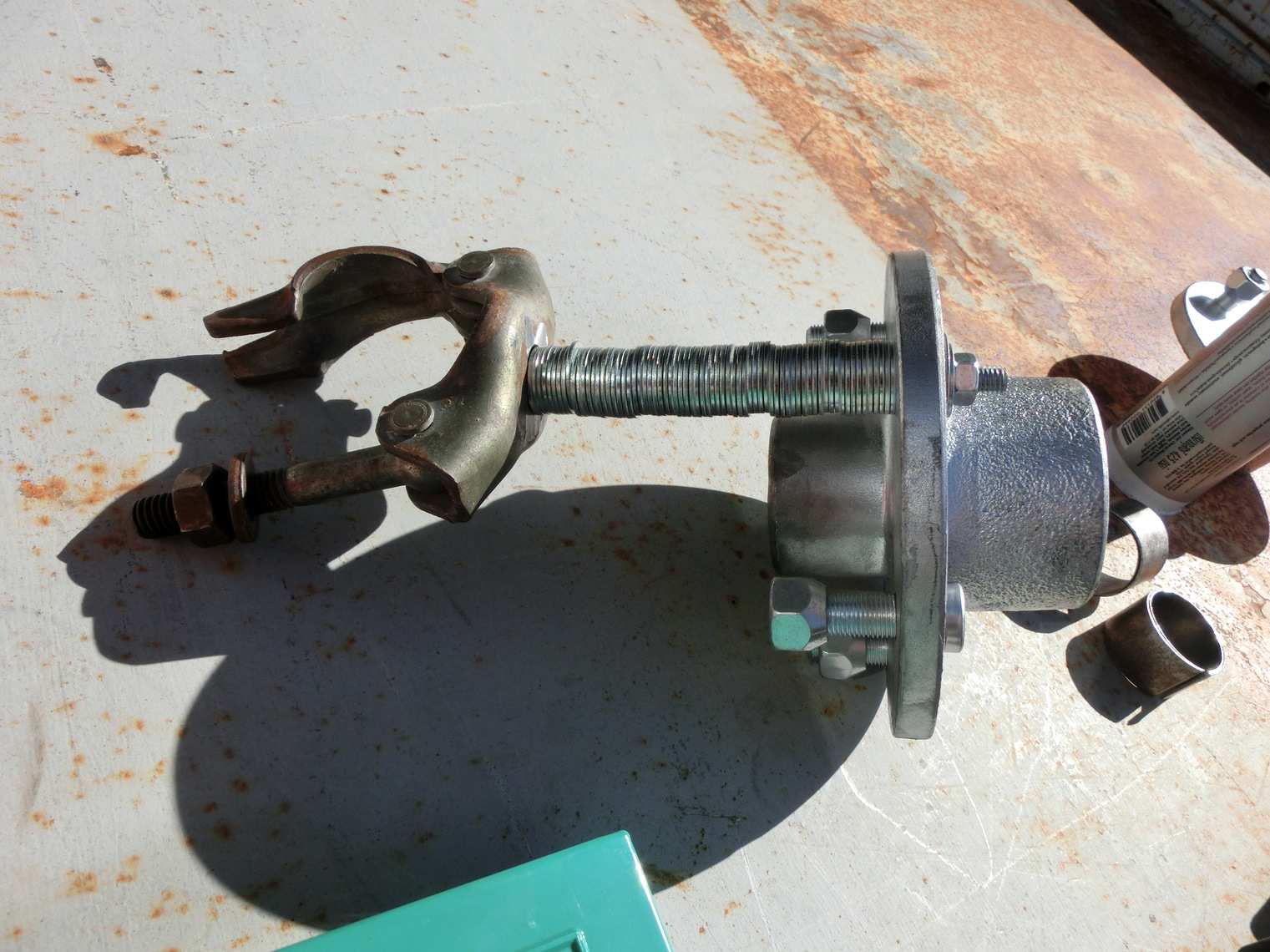
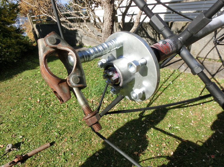
We needed reasonable solid bearings for the top and bottom of the rotating cylinder, but where would we get such a thing without spending a fortune? Turns out you can buy a trailer hub from the auto store for less than $NZ 200, and with a little metal sheathing welded into place, you can fit these snugly into a scaffold pipe.
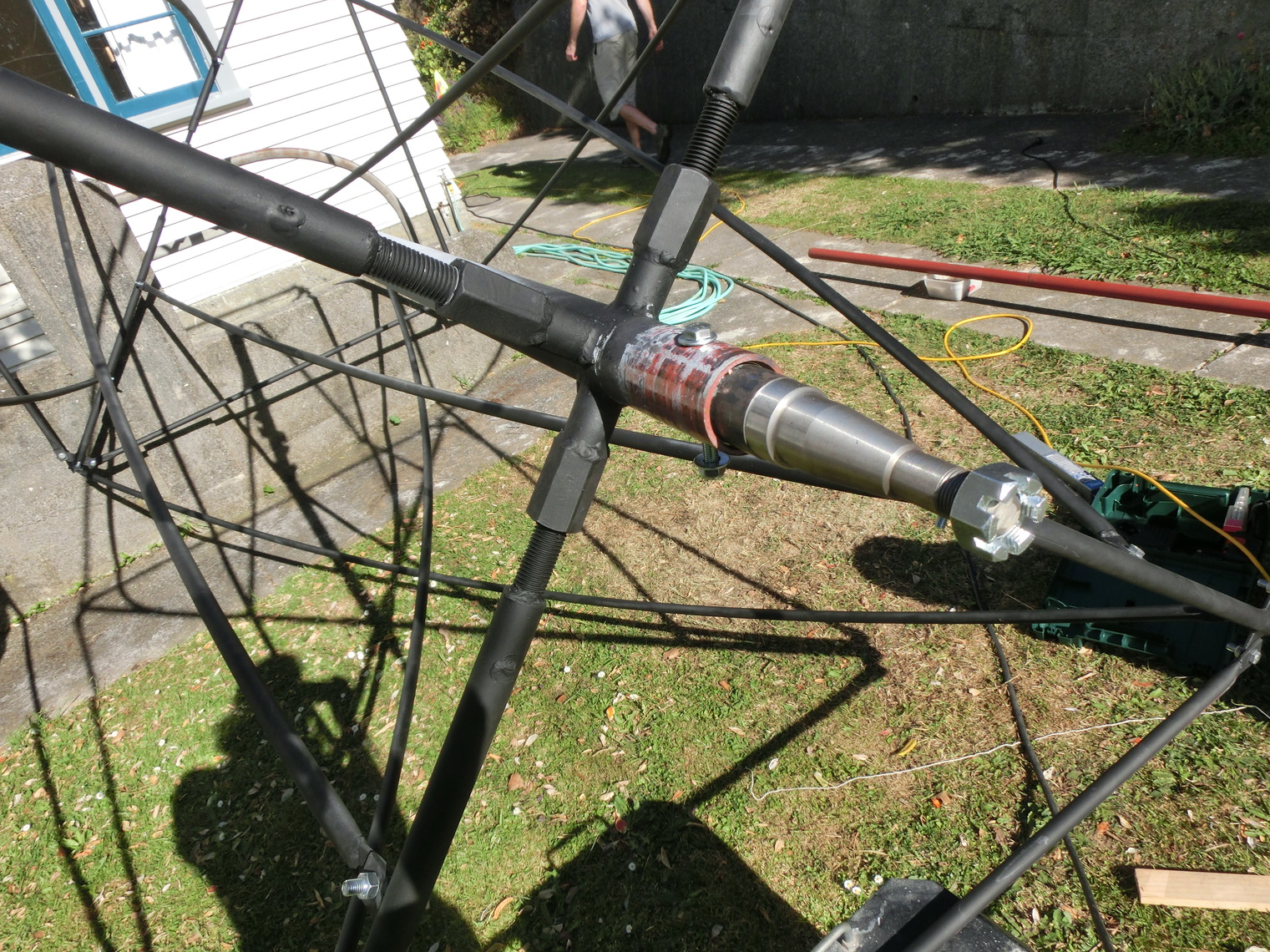
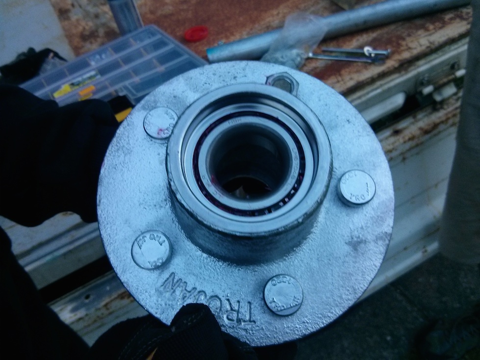
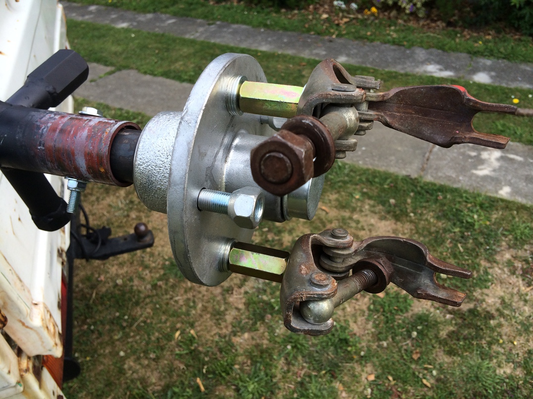
We essentially did the same thing for the bottom, but because the bottom hub would be resting on, and screwed directly to, a big piece of metal, it didn’t need the same adhoc fastenings.
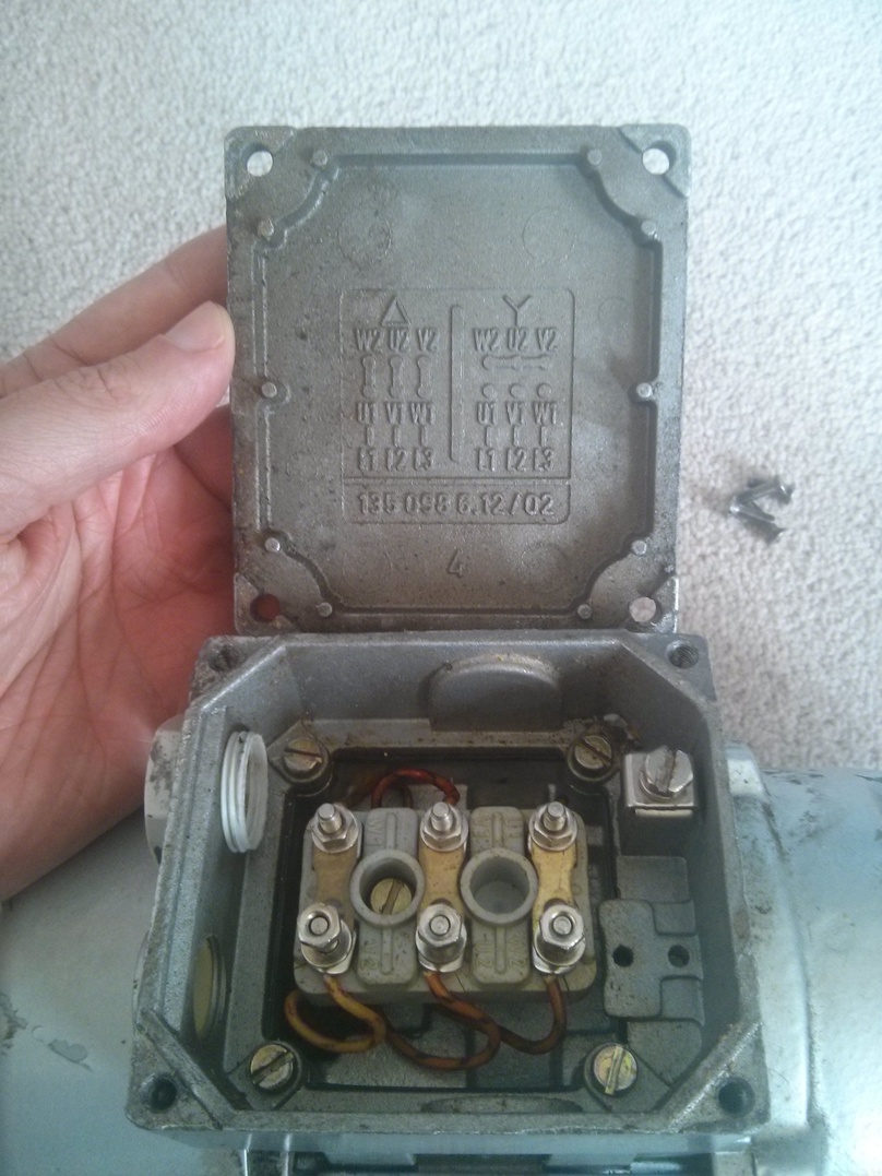
Power and Electronics
One challenge for me was how to transfer power across the axle. Fortunately, when I asked friends about this they all said “You need a slip ring!”, and lo I found one on ebay. I bought a 12x10A connection slip ring from ebay for $US 325. While we only needed 3 connections for single phase power, we figured that the slip-ring will be useful for future projects too.
The mains power is then split to 4 x 20A 5V Meanwell power supplies, since I’d used 3 of these previously for the Sensorium, and I bought spares so it’d be easy to swap them out if one was damaged. Each PSU sends power to two arms at either the top or the bottom. The reason for sending it to the bottom and top is that led strips tend to have the voltage drop if you make them too long and, and this can result in the far end looking noticeably dimmer.
Additionally I’m using Fadecandy LED controllers which have a limit of 64 leds per strip. This limit is due to the clock rate on the strips and Micah, the creator of fadecandy, wanted to optimise for great looking color and brightness using delta-sigma modulation. There is an issue open for long strip mode but once you get used to the deliciously smooth fades and vibrant colors, you soon forget about that and design your installations to handle 64 led lengths (or use different LED chips).
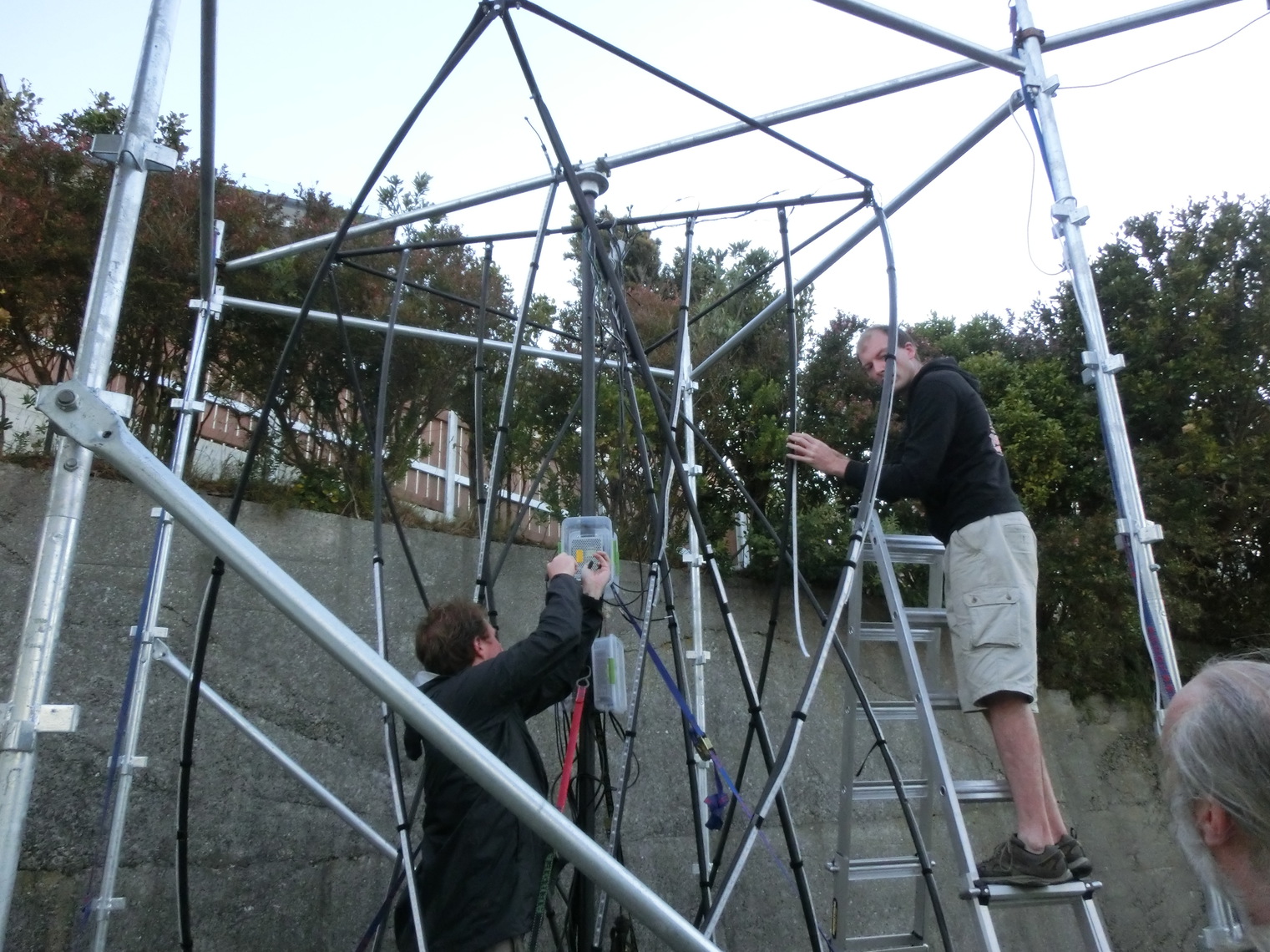
There are a total of 12 curving struts, but each one is >3m long. I was using 30 LED/m Neopixel strips, so each strut had >90 (3x30) LEDs. To use Fadecandy, I split each strut’s length of LEDs in half and sent a data signal from the top and bottom of the structure… just like I was doing with the 5V power.
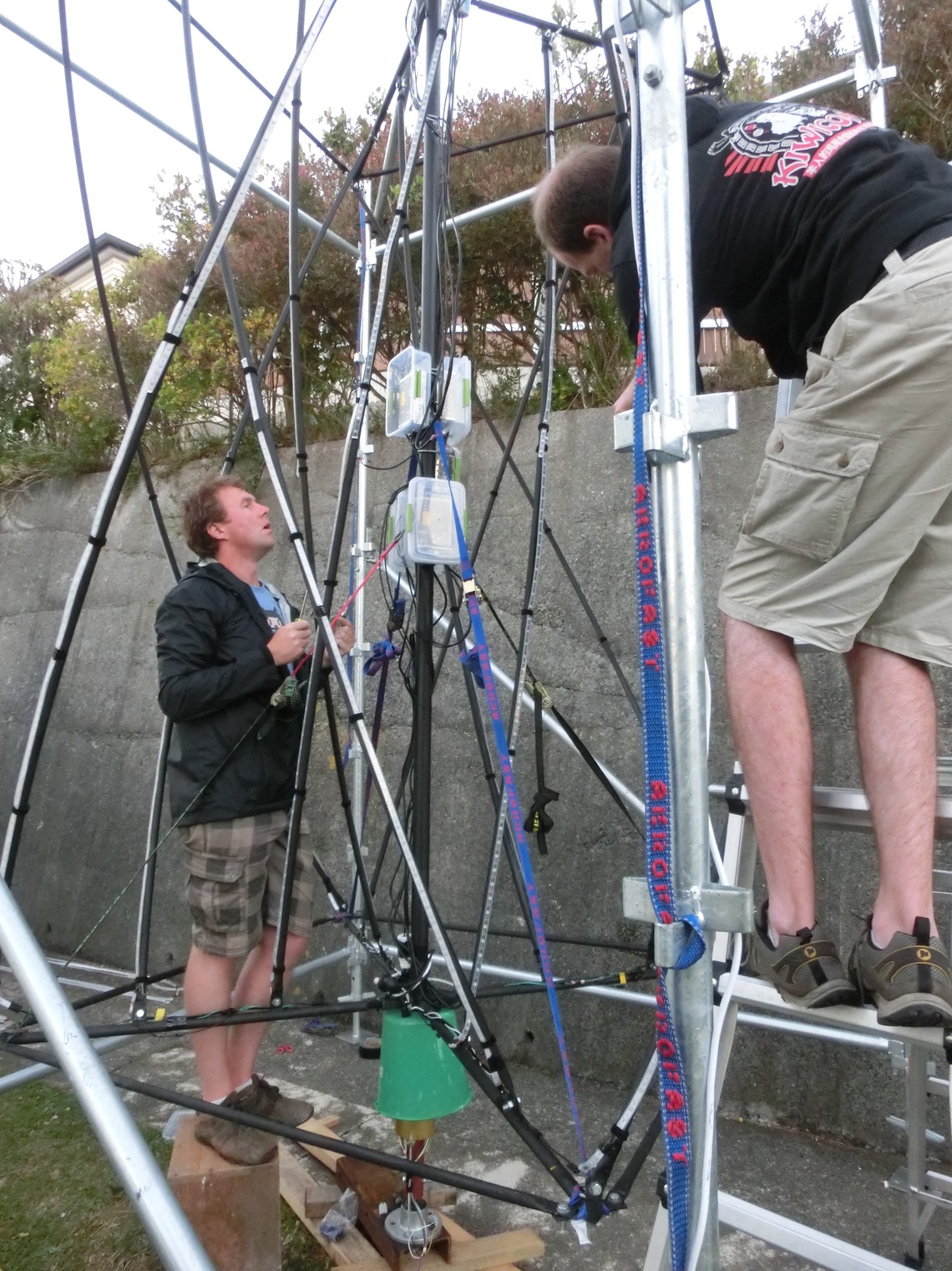
In the middle of the axle was a Raspberry Pi B, with the 4 port USB hub shield Raspiado (I’d backed the project a while ago, but didn’t quite know what I was going to use it for at the time).
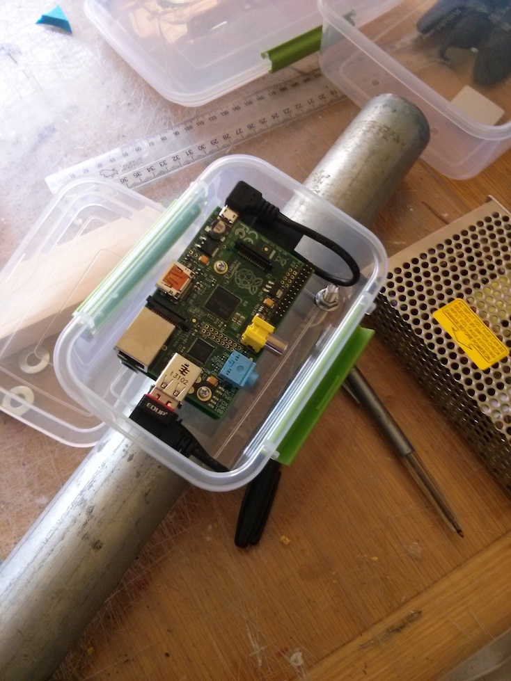
Each Fadecandy is controlled via USB, connected by a 1.5m length of USB cable to the Raspiado. The Fadecandies were placed two at the top of the axle, and two at bottom. They were mounted on a prototype board and placed in old plastic pill bottles for shelter from the elements:
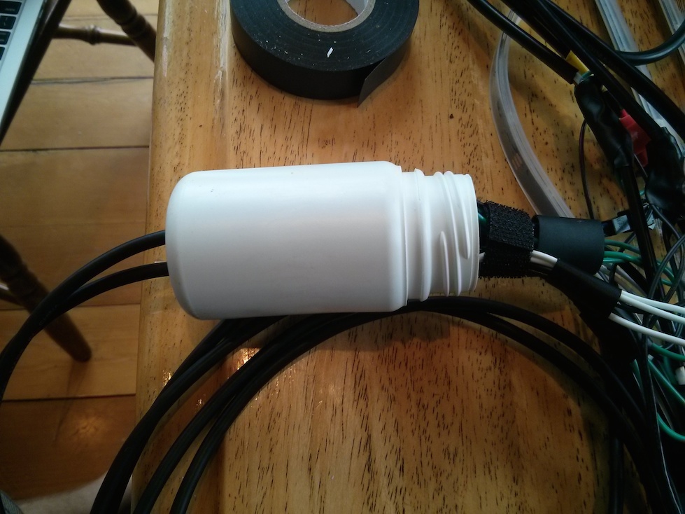
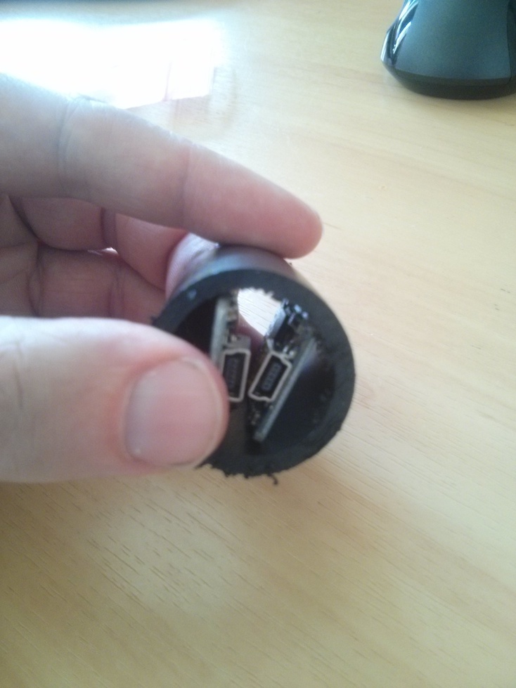
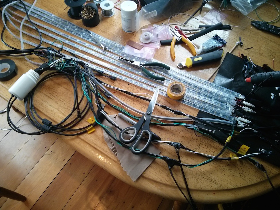
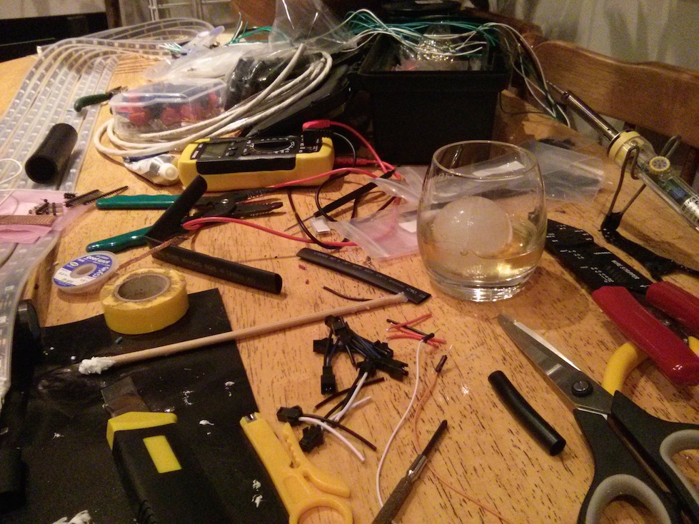
All the electronics were sealed with a less than perfect combination of sealable plastic lunchboxes, heat-shrink tubing and insulation tape. In some places I used cable glands, but only discovered them towards the end. One thing I learnt from the project, is that things are much easier once you know they exist and what they are called. If you don’t then you can end up creating jerry-rigged sub-optimal solutions. Which can be fun to fumble through, so long as you don’t have to do it for your entire project!
Software
With all the construction in place, it’s now time for a brief detour to talk about the software controlling the effects.
As I mentioned above, Fadecandy makes our life easy for controlling LEDs, and part of that ease comes from the included server software. The Fadecandy server listens for USB devices being connected, and listens for open pixel control clients. This simplifies managing the connection/disconnection of fadecandy boards, and provides an easy way to map pixel ranges from OPC channels to specific fadecandy strips.
Another bonus is a wealth of examples for creating pattern generation code. Instead of having to come up with my own framework for effects, I built upon Fadecandy’s c++ library by altering it to generate effects for multiple channels, and including a pattern randomiser.
Because the raspberry pi running the fadecandy server was being placed on the
rotating structure, I also added a small USB wifi adaptor and setup it up to
create a wifi access point on boot. And just because I like completeness, I added avahi-daemon
so I could connect to raspberry pi at tensegrity.local.
I then made the fadecandy server listen on wifi interface, so while I could run the pattern generation code directly on the raspberry pi, I could also program patterns on my laptop and stream them to the fadecandy server from my laptop. In a normal installation, the pattern generation is run locally, but it’s fun to be able to mess around with things remotely.
All code for the pattern generation is available in the github repo.
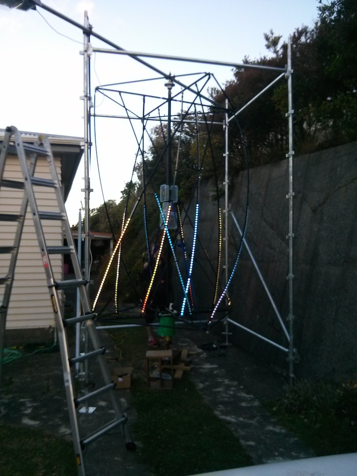
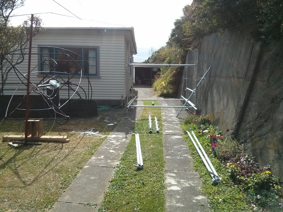
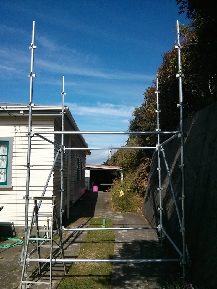
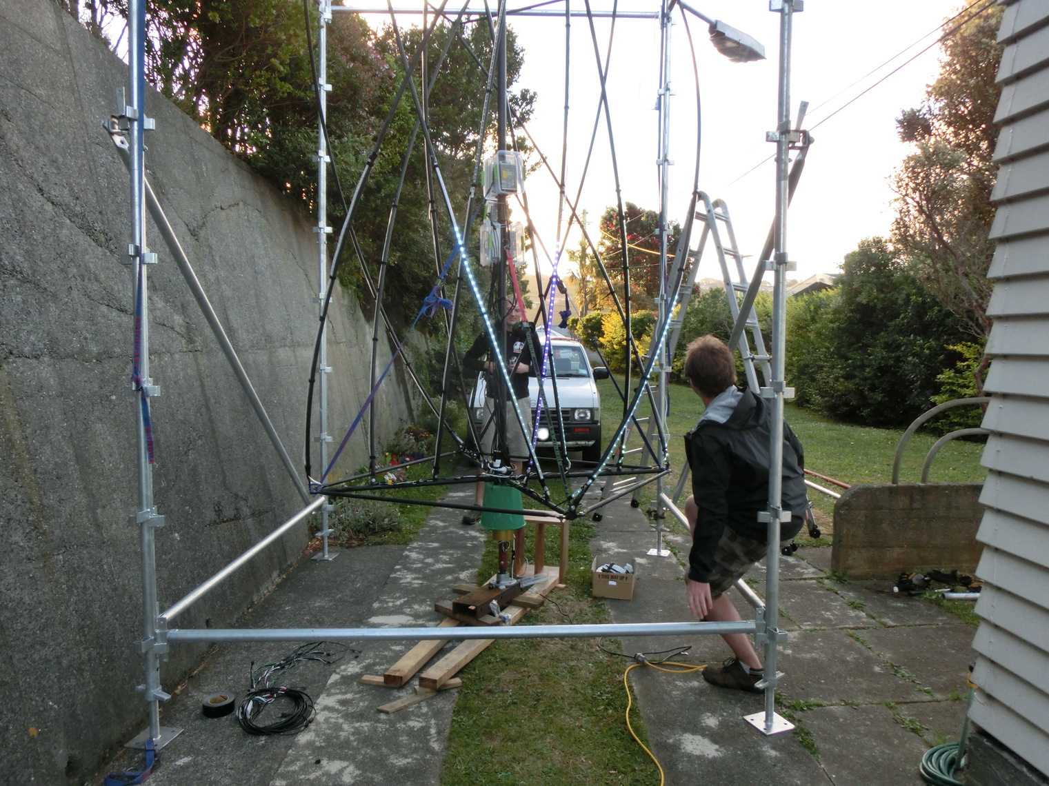
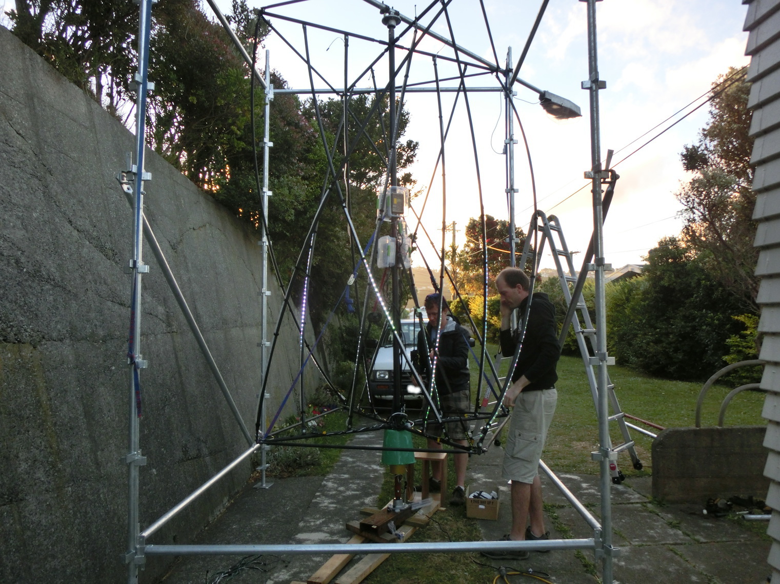
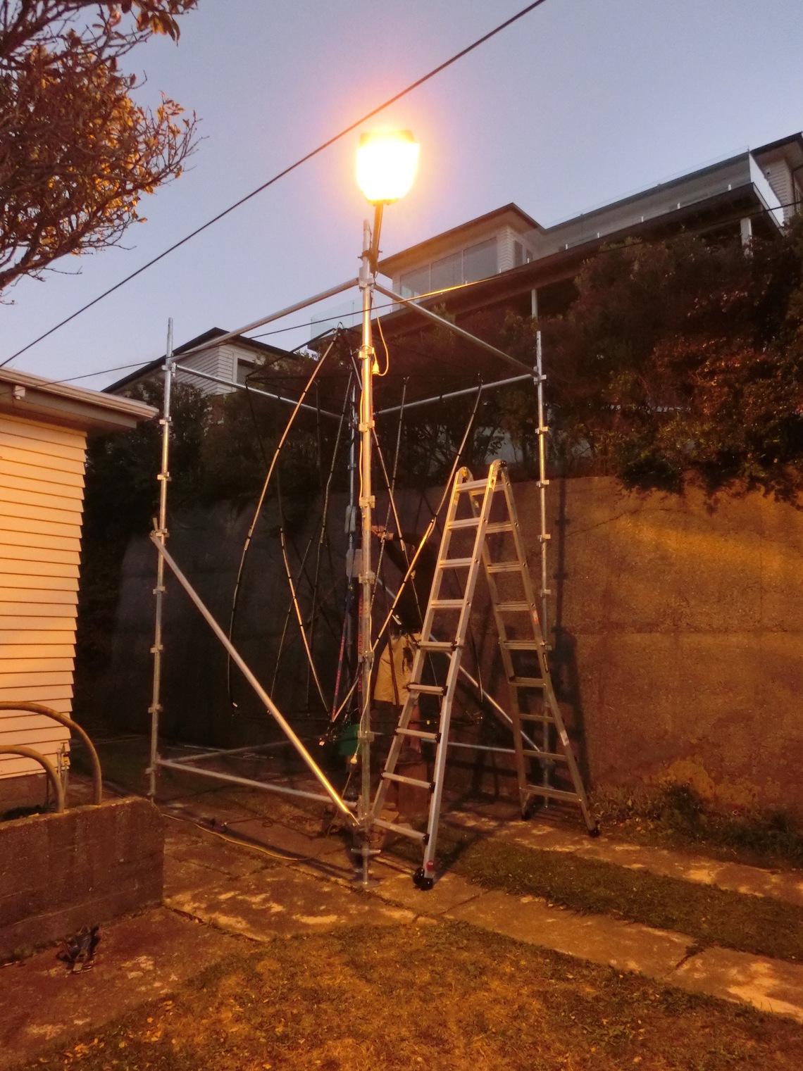
Scaffolding
With all this focus on the cylinder structure itself, it was easy to forget we still needed a way to mount it somehow. The plan early on decided on a scaffold box over mounting things on a 3m pole, because that was being a little too ambitious for our time constraints and experience.
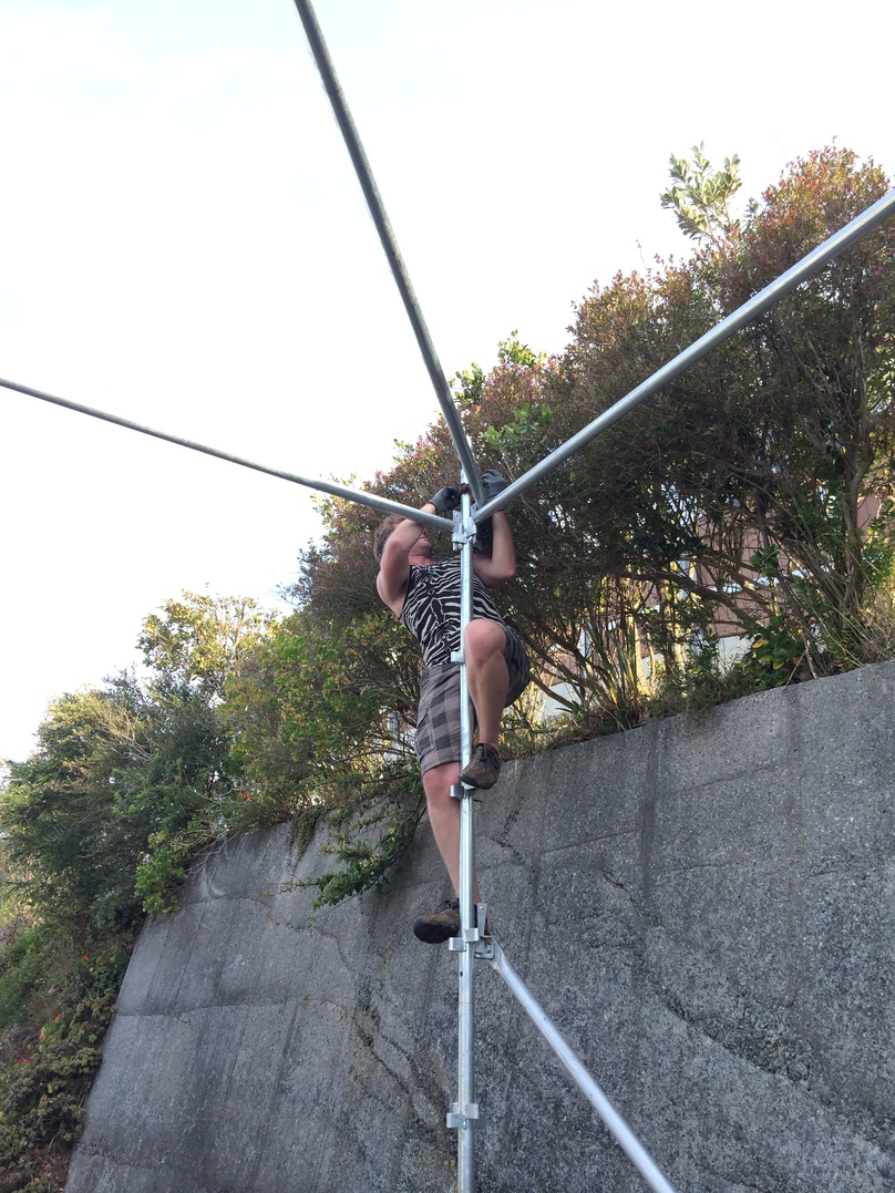
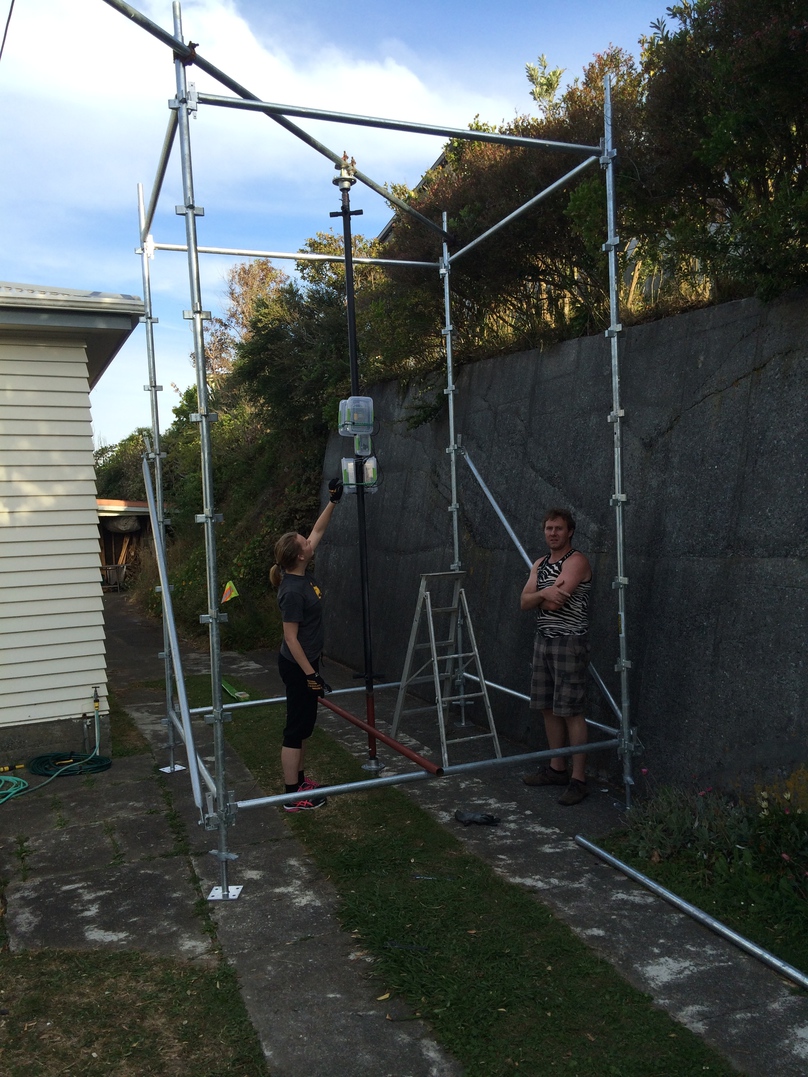
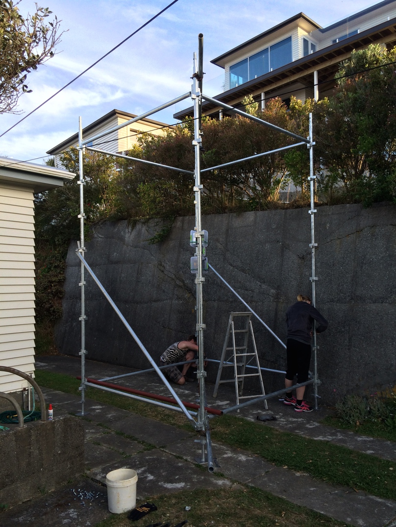
We kept an eye out for cheap scaffolding on trademe. We had one promising lead within the community, but after promising it to us they later turned around and donated to another group. Doh!
Eventually, time was running out, so I found a supplier of new scaffolding who quoted me for all the bits we’d need, and they sent it by freight to my house. Alas, this took a number of days longer than expected and when it arrived we had less than a week before kiwiburn to get things mounted.
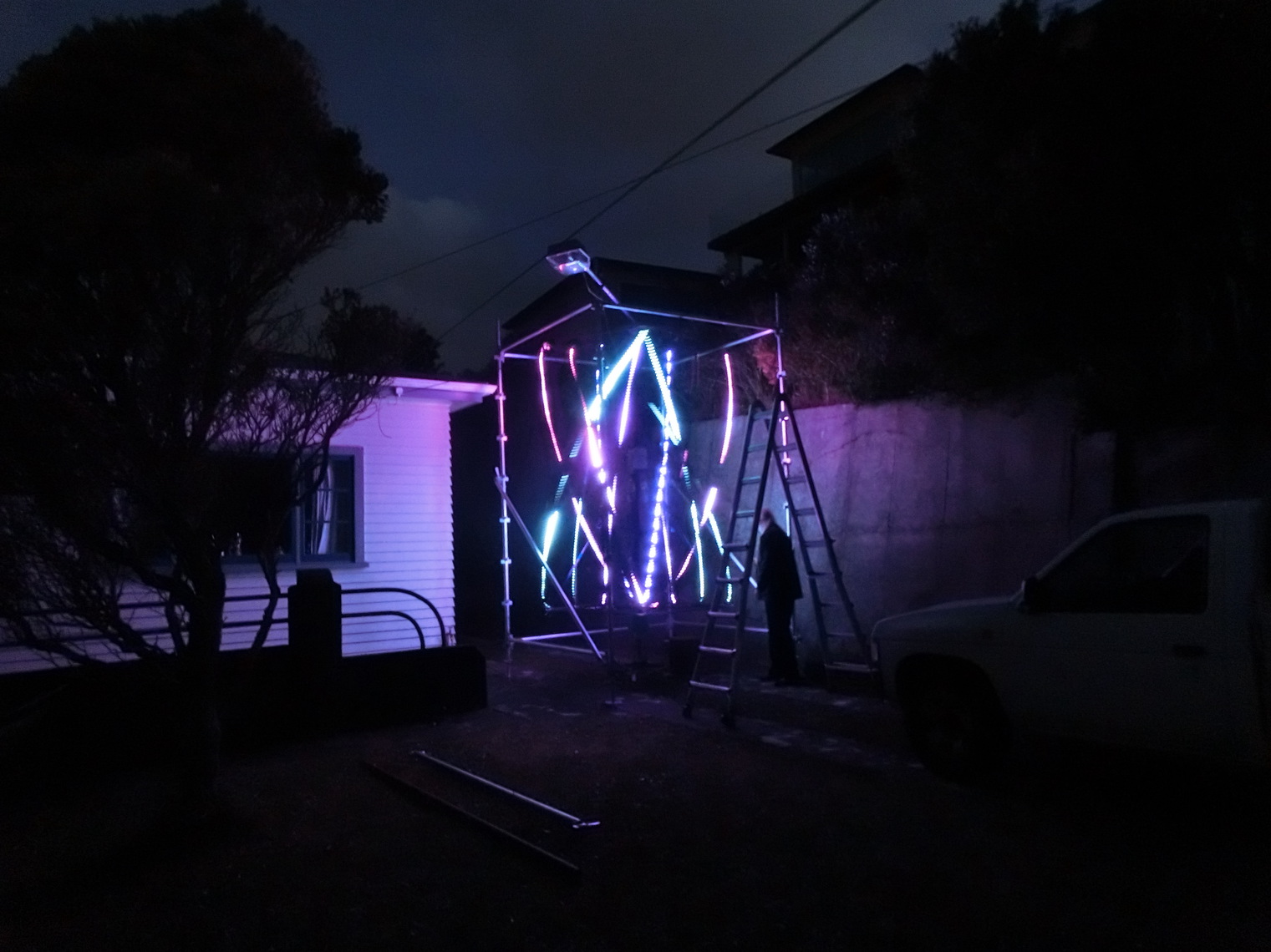
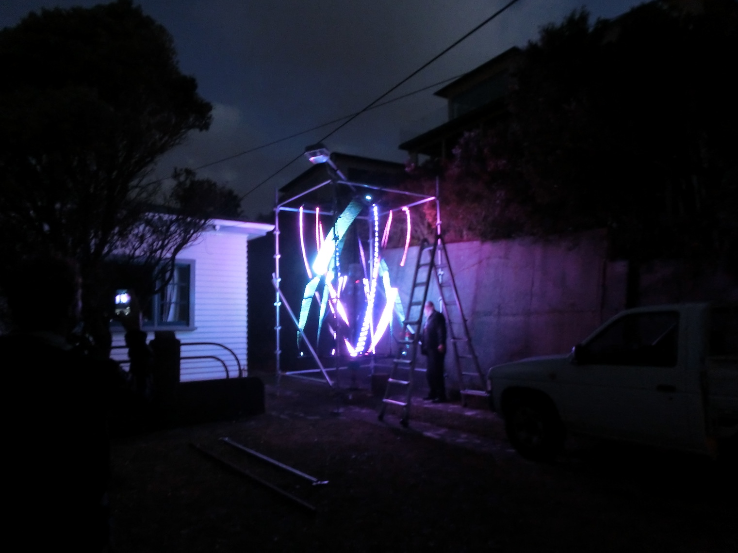
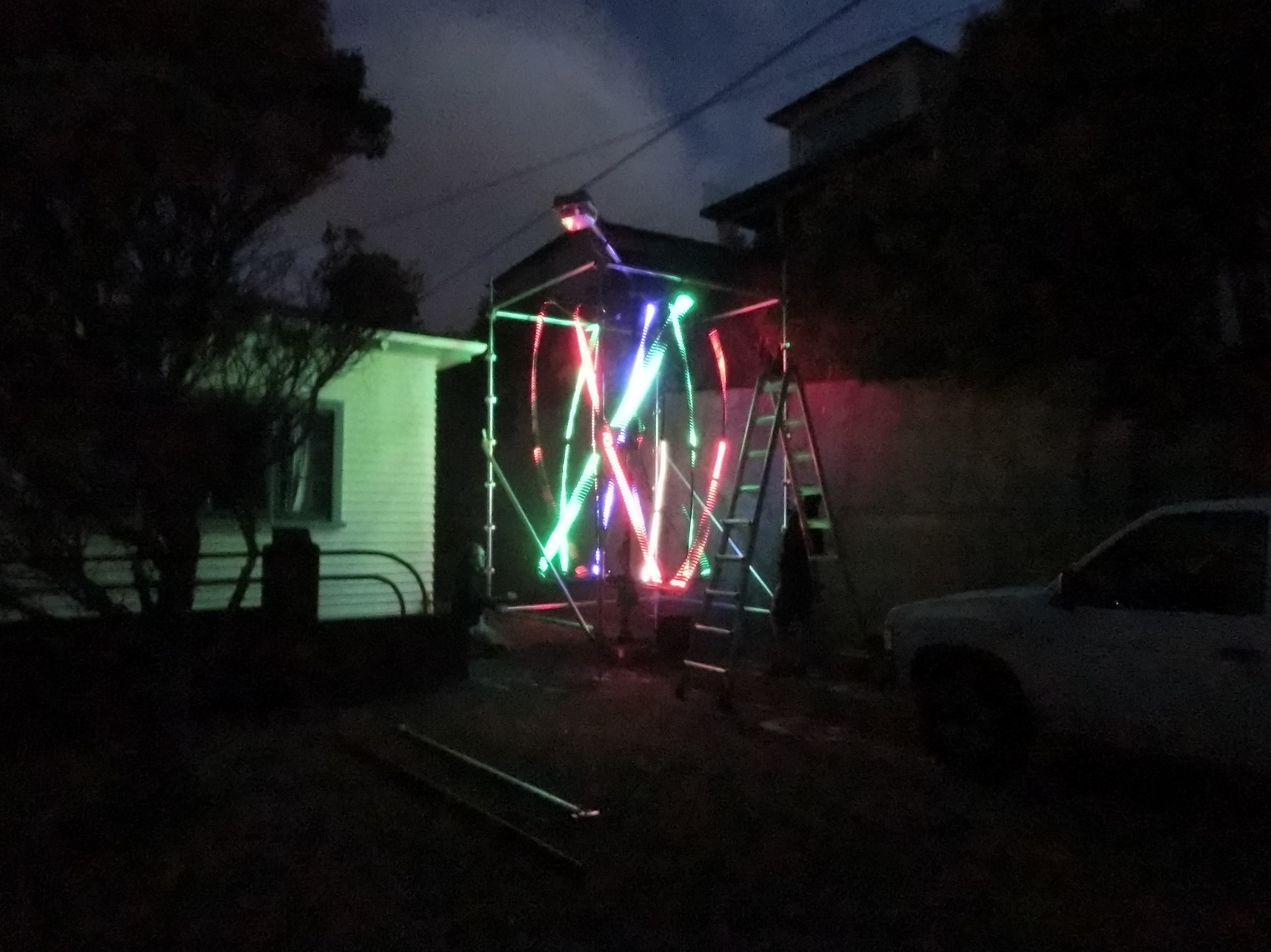
Test Run